NEC NP-M300X NP115 : ceiling plate instruction - Page 2
For Flush Mounting Applications, For Extension Column Applications - ceiling mount
 |
UPC - 805736035629
View all NEC NP-M300X manuals
Add to My Manuals
Save this manual to your list of manuals |
Page 2 highlights
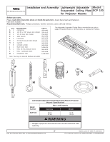
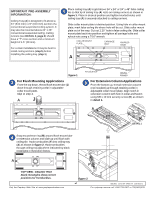
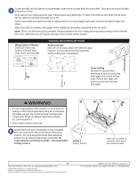
IMPORTANT PRE-ASSEMBLY INFORMATION: Ceiling Tray (A) is designed to fit above a 24" (610 mm) x 24" (610 mm) section of a conventional suspended ceiling system. It may also be mounted above 24" x 48" conventional suspended ceiling. Ceiling runners (see DETAIL 2, page 3) should have a "T" cross section and a minimum height of 1.5" (38 mm). For certain installations it may be best to install ceiling anchors (step 5) before installing the ceiling tray (step 1). Place ceiling tray (A) in grid above 24" x 24" or 24" x 48" false ceiling tile so that lip of ceiling tray (A) rests on ceiling runners as shown in figure 1. Place in desired position and tighten knurled knobs until ceiling tray (A) is securely attached to ceiling runners. Slide collar mount plate to desired position. Using hole in collar mount plate, mark false ceiling tile where hole will be cut. Slide collar mount plate out of the way. Cut out 2.25" hole in false ceiling tile. Slide collar mount plate back into position and tighten all carriage bolts and nylock nuts using a 7/16" wrench. COLLAR MOUNT PLATE CARRIAGE BOLT KNURLED KNOB A figure 1 For Flush Mounting Applications From the top down, thread flush mount tube (J) down through retaining collar in adjustable collar mount plate. Skip to step 4. A J NYLOCK NUT CEILING RUNNER For Extension Column Applications From the bottom up, thread extension column (not included) up through retaining collar in adjustable collar mount plate. Align notch in extension column with hole in collar and fasten using M5 x 10 mm security screw (K) as shown in detail 1. A K DETAIL 1 Snap escutcheon ring (M) around flush mount tube or extension column and slide up until flush with ceiling tile. Hook turnbuckles (F) into ceiling tray (A) as shown in figure 2. Hook turnbuckles through ceiling tray (A) where indicated by black rectangles in illustration below. A TOP VIEW - CEILING TRAY Black rectangles show correct positions for Turnbuckles. Visit the Peerless Web Site at www.peerlessindustries.com F figure 2 2 of 3 ISSUED: 12-16-04 SHEET #: 120-9015-1 For customer service call 1-800-729-0307 or 708-865-8870.
-
 1
1 -
 2
2 -
 3
3
 |
 |
