NEC NP-M300X NP115 : ceiling plate instruction - Page 3
Various Anchoring Methods - projector mount
 |
UPC - 805736035629
View all NEC NP-M300X manuals
Add to My Manuals
Save this manual to your list of manuals |
Page 3 highlights
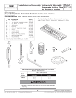
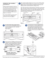
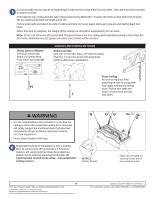
Cut tie wire (G) into four pieces of equal length. Insert wires through ends of turnbuckles. Twist each wire around itself at least four times. Drill holes for four ceiling anchors (see "Various Anchoring Methods"). Position the holes so that when the tie wires (G) are attached and taut will angle out at 15O. Pull tie wires tight and attach to ends of ceiling anchors (or truss). Again twist each wire around itself at least four times. When this step is complete, the weight of the ceiling tray should be supported by the tie wires. Note: 20' (6.1 m) of tie wire (G) is provided. If space between the true ceiling and suspended ceiling is more than 36" (914 mm), additional wire (12 gauge annealed, steel, black) will be needed. Wood Joists or Beams Drill 5/32" (4mm) dia. holes 2" (51mm) deep. Fully insert eye bolts (H). VARIOUS ANCHORING METHODS Solid Concrete Drill 1/4" (6 mm) dia. holes 1.5" (38 mm) deep. Hammer in Concrete Anchor (I) using Rawl #3250 setting tool or equivalent. Truss Ceiling No anchor required. After attaching tie wire to turnbuckle H loop upper end around ceiling truss. Pull tie wire tight and I twist it around itself at least four times. WARNING G • It is the responsibility of the installer to verify that the ceiling to which the suspended ceiling kit is anchored will safely support the combined load of all attached components (Projector Mount, Extension Column, etc.) and equipment. • Never attach hooks to filler tray. Suspended Ceiling Kit installation is now complete. After all components (Projector Mount, Extension Column, etc.) and equipment have been attached, tension the tie wires by adjusting turnbuckles (F). Load must be carried by tie wires - not suspended ceiling runners. 1.5" DETAIL 2 Ceiling Runner GG 15° G A 2' Holes are provided for electrical outlet boxes and antenna leads. 3 of 3 Visit the Peerless Web Site at www.peerlessindustries.com © 2004 Peerless Industries, Inc. All rights reserved. Peerless is a registered trademark of Peerless Industries, Inc. All other brand and product names are trademarks or registered trademarks of their respective owners. ISSUED: 12-16-04 SHEET #: 120-9015-1 For customer service call 1-800-729-0307 or 708-865-8870.
-
 1
1 -
 2
2 -
 3
3
 |
 |
