NEC PX-84VP5A 84VM5 IG - Page 6
NEC Solutions America, Inc.
 |
View all NEC PX-84VP5A manuals
Add to My Manuals
Save this manual to your list of manuals |
Page 6 highlights
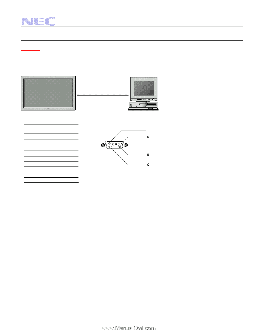
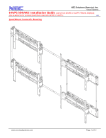
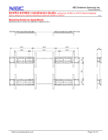
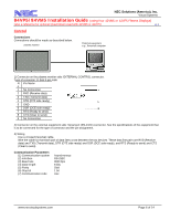
NEC Solutions (America), Inc. Visual Systems 84VP5/84VM5 Installation Guide (using four 42VM5 or 42VP5 Plasma Displays) (also a reference for optional Quad Mount used with 42VM5 or 42VP5) v1.3 Control Connections Connections should be made as described below. plasma monitor External equipment e.g., Personal computer 1) Connector on the plasma monitor side: EXTERNAL CONTROL connector. Type of connector: D-Sub 9-pin male N Pin Name o. 1 No Connection 2 RXD (Receive data) 3 TXD (Transmit data) 4 DTR (DTE side ready) 5 GND 6 DSR (DCE side ready) 7 RTS (Ready to send) 8 CTS (Clear to send) 9 No Connection 2) Connector on the external equipment side: Serial port (RS-232C) connector. See the specifications of the equipment that is to be connected for the type of connector and the pin assignment. 3) Wiring Use a crossed (reverse) cable. Wire the cable so that each pair of data lines cross between the two devices. These data line pairs are RXD (Receive data) and TXD (Transmit data), DTR (DTE side ready) and DSR (DCE side ready), and RTS (Ready to send) and CTS (Clear to send). Communication Parameters (1) Communication system (2) Interface (3) Baud rate (4) Data length (5) Parity (6) Stop bit (7) Communication code Asynchronous RS-232C 9600 bps 8 bits Odd 1 bit Hex www.necvisualsystems.com Page 6 of 14
-
 1
1 -
 2
2 -
 3
3 -
 4
4 -
 5
5 -
 6
6 -
 7
7 -
 8
8 -
 9
9 -
 10
10 -
 11
11 -
 12
12 -
13
-
14
 |
 |