NEC PX-84VP5A 84VM5 IG - Page 7
using four 42VM5 or 42VP5 Plasma Displays
 |
View all NEC PX-84VP5A manuals
Add to My Manuals
Save this manual to your list of manuals |
Page 7 highlights
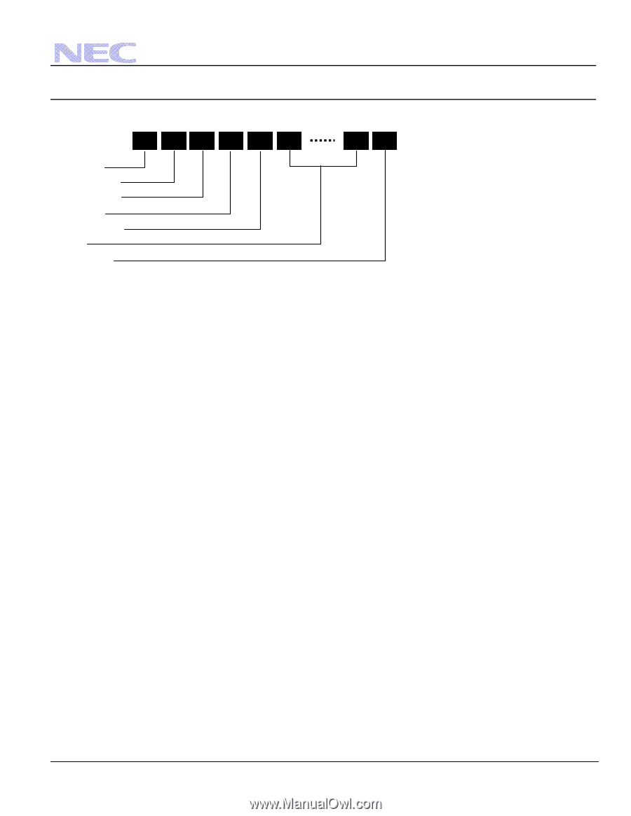
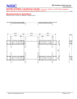
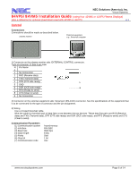
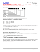
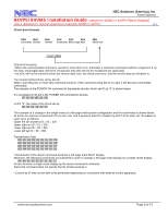
NEC Solutions (America), Inc. Visual Systems 84VP5/84VM5 Installation Guide (using four 42VM5 or 42VP5 Plasma Displays) (also a reference for optional Quad Mount used with 42VM5 or 42VP5) v1.3 Communication Format 8bit 8bit 8bit 8bit 8bit 8bit 8bit 8bit Command 1 Unit ID 1 Unit ID 2 Command 2 Data length Data Check sum Command1 Command 1, along with command 2, is a number used to distinguish each command. When making it operate using ID, bit1 and bit0 are set up as follows. Bit1,Bit0 Unit ID distinction bit 11B :Usually, a form (with no ID) 10B :Usually, a form (with no ID) 01B :Set ID 00B :Video wall ID In the case of ACK, when the lower order 4 bits is FH (as in 3FH and 7FH), this indicates that the commands and data of the supported equipment have been received. When the lower order 4 bits is BH (as in 3BH and 7BH), this indicates that unsupported commands and data have been received. Unit ID1,2 (UA1,UA2) Unit ID 1 and unit ID 2 are numbers used to identify the equipment that is to be connected. 60H is used for the plasma monitor and 80H is used for external control equipment such as a personal computer. Unit ID 1: Indicates the equipment sending the signal. When supporting Set ID by the command 1, 4 bits of low ranks of Set ID are set up. Unit ID 2: Indicates the equipment receiving the signal. When supporting Set ID by the command 1, 4 bits of higher ranks of Set ID are set up. * Set ID : it is the apparatus number assigned to each plasma monitor. Command 2 Command 2, along with command 1, is a number used to distinguish each command. Check Sum (CKS), Error Processing, and ACK The check sum described below and RS-232C odd parity are used together for a check of the received data. The check sum is the lower order 8 bits of one frame of sent or received data comprising the sum total of Command 1, Unit ID 1 and 2, Command 2, Data Length, and Data. www.necvisualsystems.com Page 7 of 14
-
 1
1 -
 2
2 -
 3
3 -
 4
4 -
 5
5 -
 6
6 -
 7
7 -
 8
8 -
 9
9 -
 10
10 -
 11
11 -
 12
12 -
13
-
14
 |
 |