Nady MGT-16 Owners Manual - Page 8
Adjusting the Squelch, Selecting the MGT-16 Receiver, Channel and IR Sync
 |
View all Nady MGT-16 manuals
Add to My Manuals
Save this manual to your list of manuals |
Page 8 highlights
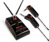
powers the unit and will not charge NiMH rechargeable batteries if installed. For battery operation the AC adapter must be disconnected. Note: For quietest optimal performance, use the AC/DC adapter as battery operation raises the noise floor around 4 dB. Generally this is only a concern when playing high-gain lead guitar. For such applications, experiment to see if slightly quieter performance with the AC/DC supply is preferred. Turn on the MGT-16 receiver by sliding the Power Switch (2) to the second position (receiver On but audio output Muted/ Attenuated), or to the third position for normal operation (receiver On and audio un‑Muted). The Power LED (12) will light up and the receiver is operational. Selecting the MGT-16 Receiver Channel and IR Sync The Frequency Select DIP Switches (4) are used for selecting one of 16 preset frequencies. Simply position the DIP switches to a desired open channel on the receiver. There should be no flickering of the RF Signal LED (10) with the transmitter off. See the MGT-16 DIP-Switch Frequency Selection Chart on page 14 for the correct switch position for each of the 16 available channels. Once you have selected the receiver frequency it can easily be downloaded to the transmitter to establish the necessary RF connection. For help in finding open channels, see RF Interference and Finding Open Channels on page 12. Adjusting the Squelch The RF Squelch (13) control should be adjusted counterclockwise to the minimum RF squelch setting at which the RF Signal LED (10) remains on while your transmitter is in normal use, up to the maximum operating range anticipated in use for your application. However, in areas of high RF activity, the squelch control may need to be adjusted clockwise. If the transmitter is off and the receiver RF Signal LED indicator is flickering or stays on continuously, the squelch should be adjusted to a higher level (clockwise for less mute sensitivity level) to stop the flickering. Be careful not to select too high a clockwise setting as this may reduce the operating range to below what is needed. A range walk test will help in selecting the proper level. If the range is not critical, note that a clockwise (maximum squelch) setting will also yield a quieter mute function, which may be desirable in certain applications. The squelch level is factory preset at maximum sensitivity and operating range (i.e. counterclockwise for minimum squelch/maximum usable range). The IR Sync Button (14) on the MGT-16 receiver is used to transfer the selected frequency info from the receiver to the transmitter for quick synchronization prior to use. Begin programming by holding the wireless transmitter's IR Receptor/Sensor Window (21) about 6-12" from the receiver's IR Synch Infrared LED Window (1). Press the IR Sync Button once to begin the IR sync download of the selected frequency to the transmitter. Note: To insure proper synchronization, the transmitter must always be just turned on, or else turned of then on again before synching. POW ER 6-12" IR PO LO RX OFF ON POWER LEVEL Note: Set controls carefully. If trim-pots are turned past minimum or maximum adjustment points they may need to be backed up to achieve desired setting. CHANNEL ACT SQ 8
-
 1
1 -
2
-
 3
3 -
 4
4 -
 5
5 -
 6
6 -
 7
7 -
 8
8 -
 9
9 -
 10
10 -
 11
11 -
 12
12 -
 13
13 -
14
-
15
-
16
 |
 |
