Nady MGT-16 Owners Manual - Page 9
Connecting Audio Output, Powering the Transmitter
 |
View all Nady MGT-16 manuals
Add to My Manuals
Save this manual to your list of manuals |
Page 9 highlights
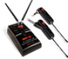
MT-16A/R Instrument Transmitter When the RF Signal LED (10) on the receiver lights up, the system frequency is properly synchronized. To change to a different frequency, reset the Frequency Select DIP Switches (4) and sync the transmitter again to the new selected frequency first, after turning the transmitter off and then on again. If no action is taken during the 10 seconds of active data transfer ( i.e., the transmitter is not turned on or properly positioned) the receiver and the transmitter units do not link and transmitter's previously programmed channel remains unchanged. Note: Only one transmitter can be used with one receiver. It is not possible to use two transmitters on the same frequency and mix the output of these transmitters into one wireless receiver. Note: The IR link is infrared light and works best when this data transfer is accomplished in a light-shielded or darker environment. It may not be successful in a brightly lit area. If the transfer fails, repeat the procedure in a darker location or somehow shield the link from outside light to successfully program the transmitter with the selected channel info from the receiver. Connecting Audio Output The MGT-16 receiver's Audio Output Jack (7) is a ¼" unbalanced line out and its level is controlled by the Volume Knob (3). Plug an audio cable with a ¼" mono (tip/sleeve) plug into the audio output jack and plug the other end into your pedal board or amplifier as you would with a direct cord from the instrument. When the Volume knob is set to maximum receiver volume setting, the system audio output is approximately +4dB higher than a direct instrument-tocord-to-amp connection. Note: As when making any connection, make sure the amplifier volume control is set at the minimum level before plugging in the receiver to avoid possible speaker damage. Your MGT-16 receiver is now operational and ready to use. Once you have completed the above steps, proceed to the following instructions for the MT-16A/R Instrument transmitter. Powering the Transmitter The MT-16A/R Instrument transmitter requires one AAA size battery (25). To install the battery, push the locking tabs on the Battery Cover (25) and push out to expose the Battery Compartment (22). Insert one fresh AAA battery according to the correct polarity as indicated on the transmitter body. Close the battery cover, ensuring the cover is snapped shut. A fresh AAA alkaline battery generally provides up to 6-8 hours of operation, but in order to ensure optimal performance it is recommended that the battery be replaced after six hours of use or as indicated by the Low Battery Indicator (20). To turn on the transmitter, slide the Power Switch (17) in the direction of the arrow. The Low Battery Indicator will flash once. The unit is now on and the receiver's RF Signal LED (10) will light up if the transmitter has been frequency synchronized to the receiver's selected frequency as per below. As the batteries weaken, the Low Battery Indicator will flash to warn that the battery level is too low and should be replaced as soon as possible. To preserve battery life, turn the transmitter Off when not in use. To turn the transmitter Off, slide the Power Switch in the opposite direction of the arrow. The transmitter has a 15dB Pad (18) On/Off switch which can be selected to attenuate high output instrument pick-up levels if needed to reduce distortion through the system. To turn On, slide the switch in the direction of the arrow. Turning opposite the arrow indication is for standard 1:1 gain operation and is recommended for normal, optimal low-noise operation. The transmitter has an Internal Audio Level Adjust (23) to set the audio deviation level. It is accessed by inserting a small screwdriver into the slot. Turning this 9
-
 1
1 -
2
-
3
-
 4
4 -
 5
5 -
 6
6 -
 7
7 -
 8
8 -
 9
9 -
 10
10 -
 11
11 -
 12
12 -
 13
13 -
 14
14 -
15
-
16
 |
 |
