Nady U-41 Manual - Page 4
U-41 Quad Receiver - quad 2
 |
View all Nady U-41 manuals
Add to My Manuals
Save this manual to your list of manuals |
Page 4 highlights
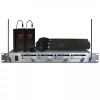
U-41 QUAD RECEIVER Rack-mounting the Receiver The Nady U-41 QUAD UHF receiver has built-in brackets for rackmounting. Simply attached the unit to the rack and tighten the unit with screws. (Note: Do not mount the receiver in a rack directly above an amplifier or other source of high heat. This could degrade the performance of the U-41 QUAD. Always ensure adequate airflow and heat dissipation in any rack configuration.) Antennas Install antennas by connecting the two antennas (1) included with your system to the two RF BNC connectors (2) located on the left and right front of the U-41 QUAD receiver. The optimal positions of the antennas are 90 degrees from the receiver pointing up position. For maximum range, it is always best to maintain a line of sight (no obstructions) between the receiver antennas ant the transmitter at all time whenever possible. Powering the Receiver Power the receiver by plugging the provided AC adaptor (3) (16.5VDC/0.4A) plug into the DC INPUT jack (4) on the back of the receiver. Then plug the adapter into an AC outlet. (Note: Any 16.5VDC source with 400mA capacity can also be used.) Turn volume controls (5) of all channels counterclockwise to minimum settings. Once the receiver is connected to a power source, press the power switch (6) to the ON position. The TX indicator LEDs (7) on the front panel of the receivers will not light up at this time, until one or more of the four channels is receiving a signal from your system's transmitters. To turn OFF, press the power switch (6) to the OFF position. The receiver will be off. Adjusting Mute In normal operation, each channel's mute control (8) should be turned clockwise fully to the factory preset RF level of 1uV for maximum sensitivity. Doing so sets each receiver for maximum range. However, in case of high RF activity, the mute should be adjusted. If, with a transmitter turned off, its corresponding LED on the receiver front panel flickers or stays on, the mute control of the corresponding channel should be turned counterclockwise until the LED extinguishes. For each of the four channels, when the mute is properly adjusted, the corresponding LED will light only when the system's transmitter is turned on. Turning the mute clockwise too far will result in reduced range, but yield a quieter signal during dropout or at the end of the operating range. Audio Level and Peak LED indicator The U-41 QUAD receiver is equipped with a 5-segment LED AF LEVEL (9) display for each channel. The red LED on the right of these displays is the audio peak indicator. Note that the peak red LED will light with a strong audio signal from the transmitter. Occasional flickering of the peak LED on loud input signals to the transmitter is normal. However, If the peak LED lights continuously, the volume into the transmitter should be decreased or audio distortion may result. Connecting Audio Outputs The U-41 QUAD audio output stage of each channel is configured for XLR balanced microphone fixed level, with an output impedance of 600 ohms, to accommodate both balanced and unbalanced mics. The XLR outputs (10) are preset at the factory and are not adjustable with the receiver volume controls. For each channel you wish to use, insert an audio cord with a female XLR plug into its audio jack on the back of the receiver. Plug the other end cord into your amplifier, effects or mixing board. The volume level of each receiver should be adjusted by the mixing board. 4
-
 1
1 -
 2
2 -
 3
3 -
 4
4 -
 5
5 -
 6
6 -
 7
7 -
 8
8 -
 9
9 -
 10
10 -
11
-
12
-
13
-
14
-
15
-
16
 |
 |
