Nady W-1KU Manual - Page 9
Installing Antennas, Powering the Receiver, Adjusting the Squelch, Audio Level and Peak LED
 |
View all Nady W-1KU manuals
Add to My Manuals
Save this manual to your list of manuals |
Page 9 highlights
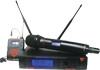
Installing Antennas Install antennas by connecting the two Antennas (19) included with your system to the two RF Connectors (18) located on the back of your W-1KU receiver. The optimal positions of the antennas are 45 degrees from the receiver and 90 degrees from each other. For maximum range, it is always best to maintain a line-of-sight (no obstructions) between the receiver antennas and the transmitter at all times whenever possible. Powering the Receiver To power the receiver, plug the provided AC/DC Power Supply (14) adapter into the DC Input Jack (13) on the back of the receiver, then plug the adapter into an AC outlet. Note: Any 15-18VDC source with minimum 400mA capacity can also be used. Connect either the 1⁄4" Unbalanced Line Out (17) or XLR Balanced Mic Out (15) to your mixing board, effect, or amplifier (see Connecting the Audio Equipment). To turn on, press the Power Button (12) for two seconds. The LCD Display (2) will light (showing Group, Channel, RF Level Meter, Diversity, and Output Volume). The 5-segment AF LED Tree (1) will display the received audio level when the transmitter is activated and audio transmitted. To turn off, press the Power button for three seconds and release. The receiver will turn off. Adjusting the Squelch The RF Squelch (16) simultaneously controls both of the A and B True Diversity receiver mute sections. The control should be adjusted counterclockwise to the minimum RF squelch setting at which the RF Level Meter (7) and the Diversity Indicator (3) will remain on while your transmitter is in normal use, up to the maximum operating range anticipated in use for your application. However, in areas of high RF activity, the squelch control may need to be adjusted clockwise. If the transmitter is off and the receiver signal and the diversity indicators are flickering or stay on continuously, the squelch should be adjusted to a higher level (clockwise for less mute sensitivity level) to stop the flickering. Be careful not to select too high a clockwise setting as this may reduce the operating range to below what is needed. A range walk test will help in selecting the proper level. If the range is not critical, note that a clockwise (maximum squelch) setting will also yield a quieter mute function, which might be desired in certain applications. The squelch level is factory preset at maximum sensitivity and operating range (i.e. counterclockwise for minimum squelch level-maximum usable range). Audio Level and Peak LED Indicator The W-1KU receiver has a 5-segment AF Level LED Display (1) that lights up sequentially, indicating the level of the audio signal from the transmitter. Occasional flickering of the top (red) Peak LED on loud inputs to the transmitter is normal. If the Peak LED lights continuously decrease the input audio level to the transmitter or overload distortion may result. Connecting the Audio Output The W-1KU audio output is set up for either balanced mic (fixed level) or unbalanced line (adjustable level). The Unbalanced Line Out is controlled by the or volume control buttons. The receiver Volume Display (6) will indicate the level selected. For balanced output, plug an audio cable with an XLR connector into the XLR Balanced Mic Out (15) socket and plug the other end into your mixing board or amplifier. For unbalanced output, plug an audio cable with a 1⁄4" mono (Tip/Sleeve) plug into the Unbalanced Line Out (17) jack and plug the other end into your mixing board or amplifier. When using the BT-1KU instrument transmitter system, connect the Unbalanced Line Out directly to your instrument amp or preamp. 9
-
 1
1 -
2
-
3
-
 4
4 -
 5
5 -
 6
6 -
 7
7 -
 8
8 -
 9
9 -
 10
10 -
 11
11 -
 12
12 -
 13
13 -
 14
14 -
15
-
16
-
17
-
18
-
19
-
20
 |
 |
