Netgear FS104 Installation Guide - Page 10
Prepare the Site, Install the Switch, Connect Devices to the Switch - guide
 |
View all Netgear FS104 manuals
Add to My Manuals
Save this manual to your list of manuals |
Page 10 highlights
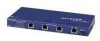
Prepare the Site Before you begin installing your switch, prepare the installation site. Make sure your operating environment meets the operating environment requirements of the equipment. Characteristic Temperature Operating humidity Ventilation Operating conditions Power Requirement Ambient temperature between 0G and 40G C (32G and 104G F). No nearby heat sources such as direct sunlight, warm air exhausts, or heaters. Maximum relative humidity of 90%, noncondensing. Minimum 2 inches (5.08 cm) on all sides for cooling. Adequate airflow in room or wiring closet. At least 6 feet (1.83 m) to nearest source of electromagnetic noise (such as photocopy machine or arc welder). Adequate power source within 6 feet (1.83 m). Install the Switch To install your switch on a flat surface, you do not need any special tools. Be sure the switch is positioned with at least 2 inches of space on all sides for ventilation. To install the switch on a wall, measure the distance between the mounting holes on the back of the switch and mark the wall to match the location of the mounting holes on the switch. At the marks, screw into the wall the two screws in the mounting kit included in your package contents. Choose a location that is near the devices to be connected, is close to an electrical outlet, and provides at least 2 inches of space all around the switch for ventilation. Connect Devices to the Switch Before connecting the switch, be sure you review "Applications" for to determine the appropriate configuration for your networking needs. To connect the switch: 1. Connect the devices to the 10/100 Mbps ports on the switch, using Category 5 UTP cable and an RJ-45 plug. Note: Ethernet specifications limit the cable length between your PC or server and the switch to 328 feet (100 meters). 2. Set the Normal/Uplink push button. The Normal/Uplink push button eliminates the need to use a crossover twisted pair cable for daisy-chaining or cascading. Use the following guidelines to configure port 1 and port 2 on the Model FS102 switch, port 4 on the Model FS104 switch, or port 8 on the Model FS108 switch for uplink or normal wiring: • Configure the port for normal wiring if the port is to be connected to an uplink-wired device, such as a network station or a PC. • Configure the port for uplink wiring if the port is to be connected to a normal-wired device, such as a 100 Mbps hub or another switch. The remaining (normal) ports on the switch cannot be configured for uplink wiring. If you are using one of these ports to connect to another normal port, you must use a crossover twisted pair cable to connect the two ports. Refer to "Cable and Connector Information" for information about crossover twisted pair cable and straight-through twisted pair cable. Model FS102, Model FS104, Model FS108 Fast Ethernt Switch Installation Guide
-
 1
1 -
2
-
3
-
4
-
 5
5 -
 6
6 -
 7
7 -
 8
8 -
 9
9 -
 10
10 -
 11
11 -
 12
12 -
 13
13 -
 14
14 -
 15
15 -
16
-
17
 |
 |
