Netgear GS108T GS108T Hardware manual - Page 25
Installation, Step 1: Preparing the Site
 |
UPC - 606449051377
View all Netgear GS108T manuals
Add to My Manuals
Save this manual to your list of manuals |
Page 25 highlights
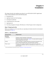
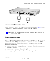
Chapter 4 Installation This chapter describes the installation procedures for your NETGEAR GS108T Gigabit Smart Switch. Switch installation involves the following steps: 1. Preparing the site 2. Applying footpads and wall mounting 3. Checking the installation 4. Connecting devices to the switch 5. Applying power 6. Switching management through a Web Browser or Utility Program (initial configuration) Step 1: Preparing the Site Before you install your switch, ensure that your operating environment meets the environmental requirements in Table 4-1. Table 4-1. Site Requirements Characteristics Requirements Mounting Installations Access Power source Desktop: provide a flat table or shelf surface Wall-mount: select a location (see "Access"). You also need the mounting screws supplied with your switch. Locate the switch in a position that lets you access the front panel RJ-45 ports, view the front panel LEDs, and access power connector. Provide a power adapter (included)a. Ensure that the AC outlet is not controlled by a wall switch, which can accidentally turn off power to the outlet and the switch. a. Power specifications for the switch are shown in Appendix B, "Technical Specifications" 4-1 v1.0, March 2007
-
 1
1 -
2
-
3
-
4
-
5
-
6
-
7
-
8
-
9
-
10
-
11
-
12
-
13
-
14
-
15
-
16
-
17
-
18
-
19
-
 20
20 -
 21
21 -
 22
22 -
 23
23 -
 24
24 -
 25
25 -
 26
26 -
 27
27 -
 28
28 -
 29
29 -
 30
30 -
31
-
32
-
33
-
34
-
35
-
36
-
37
-
38
 |
 |
