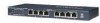
Netgear GS108T GS108T Hardware manual - Page 27
Step 5: Applying Power, Because the NETGEAR GS108T Gigabit Smart Switch has no ON/OFF switch - grounding
 |
UPC - 606449051377
View all Netgear GS108T manuals
Add to My Manuals
Save this manual to your list of manuals |
Page 27 highlights
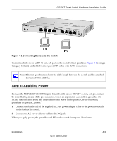
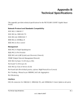
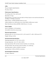
GS108T Smart Switch Hardware Installation Guide Figure 4-1 Connecting Devices to the Switch Connect each device to an RJ-45 network port on the switch's front panel (see Figure 4-1) using a Category 5 (Cat5) unshielded twisted-pair (UTP) cable with RJ-45 connectors. Note: Ethernet specifications limit the cable length between the switch and the attached device to 100 m (328 ft.). Step 5: Applying Power Because the NETGEAR GS108T Gigabit Smart Switch has no ON/OFF switch, AC power must be controlled by means of the power adapter. Select an appropriate unswitched, grounded AC facility outlet so as to avoid any future inadvertent power interruptions. Use the following procedure to apply AC power: 1. Connect the female end of the supplied IEC AC power adapter cable to the power receptacle on the back of the switch. 2. Connect the AC power adapter cable to the DC jack. When you apply power, the green Power LED on the switch front panel illuminates. Installation 4-3 v1.0, March 2007
-
 1
1 -
2
-
3
-
4
-
5
-
6
-
7
-
8
-
9
-
10
-
11
-
12
-
13
-
14
-
15
-
16
-
17
-
18
-
19
-
20
-
21
-
 22
22 -
 23
23 -
 24
24 -
 25
25 -
 26
26 -
 27
27 -
 28
28 -
 29
29 -
 30
30 -
 31
31 -
 32
32 -
33
-
34
-
35
-
36
-
37
-
38
 |
 |
