Netgear GS110T GS110T Hardware Installation Guide - Page 12
GS110T Back-Panel Configuration, LED Designations, Port LEDs
 |
View all Netgear GS110T manuals
Add to My Manuals
Save this manual to your list of manuals |
Page 12 highlights
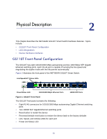
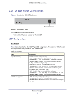
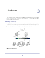
NETGEAR GS110T Smart Switch GS110T Back-Panel Configuration Figure 3 illustrates the GS110T back panel. Figure 3. GS110T Back Panel The back panel contains the following: • External 12V/1A power adapter for the GS110T Power Connector LED Designations Port LEDs Table 1 describes the RJ-45 and SFP port LED designations. There are two LEDs for each RJ-45 port. Each SFP port has its own indication LED. Table 1. Port LEDs LED Speed/Link/Activity SFP Port Indicate LED Designation 100 Mbps Link/ACT LED (Left LED): • Off = No 100 Mbps link is established on the port. • Solid Green = A valid 100 Mbps link is established on the port. • Blinking Green = Packets transmission/received on the port. 10 Mbps Link/ACT LED (Right LED): • Off = No 10 Mbps link is established on the port. • Solid Green = A valid 10 Mbps link is established on the port. • Blinking Green = Packets transmission/received on the port. 1000 Mbps Link/ACT LED (Both LEDs): • Off = No 1000 Mbps link is established on the port. • Solid Green = A valid 1000 Mbps link is established on the port. • Blinking Green = Packets transmission/received on the port. • Off = No link is established on the port. • Solid Green = A valid link is established on the port. • Flashing Green = Packet transmission or reception is occurring on the port. Physical Description 12
-
 1
1 -
2
-
3
-
4
-
5
-
6
-
 7
7 -
 8
8 -
 9
9 -
 10
10 -
 11
11 -
 12
12 -
 13
13 -
 14
14 -
 15
15 -
 16
16 -
 17
17 -
18
-
19
-
20
-
21
-
22
-
23
-
24
-
25
-
26
-
27
-
28
 |
 |
