Nikon SU-800 Wireless Speedlight Commander Users Manual - English - Page 20
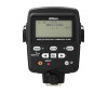
SU-800's LCD panel and icons, Icons in close-up flash operation
 |
View all Nikon SU-800 Wireless Speedlight Commander manuals
Add to My Manuals
Save this manual to your list of manuals |
Page 20 highlights
Speedlight parts, their functions, and accessories SU-800's LCD panel and icons Icons on the SU-800's LCD panel show the status of the operations set. These icons vary depending on the settings and the combination of camera and flash units in use. • The below illustrations are for reference only and may differ to the actual display. Icons in close-up flash operation Display in TTL mode 1 Wireless Flash A control signal is sent from the SU-800 to the remote flash units such as the SB-R200. 2 Close-up Mode Close-up function is set to "activated." 3 Monitor Preflashes Just before the flash fires, the Speedlight fires a series of imperceptible preflashes to collect necessary data for actual flash firing. 4 TTL Mode Measuring the flash illumination reflected back from the subject, the camera automatically controls the flash output level to give the correct exposure. 5 Auto FP High-Speed Sync Auto FP High-Speed Sync. is available when the SU-800 is connected to cameras compatible with Auto FP HighSpeed Sync. (p. 96). 6 Low Battery-power Replace the battery. 7 Flash Output Level (Group A) Visually indicates the group A's flash output level in the TTL mode. Display in M (manual) mode 8 Flash Output Level (Group B) Visually indicates the group B's flash output level in the TTL mode. 9 Flash Output Level Ratio (Groups A : B) Indicates the flash output level ratio between groups A and B in the TTL mode. 0 Channel Represents the communication channel number through which the SU-800 and SB-R200 exchange data. ! Flash Output Level Compensation (Groups A, B) Represents flash output level compensation for groups A and B in the TTL mode. @ CLS-compatible camera The SU-800 is connected to cameras compatible with CLS. # Manual Flash The flash always fires at a specified output in combination with the aperture and light output level (guide number). $ Manual Flash Output Level Represents flash output level for each group in Manual flash mode. 20
-
 1
1 -
2
-
3
-
4
-
5
-
6
-
7
-
8
-
9
-
10
-
11
-
12
-
13
-
14
-
 15
15 -
 16
16 -
 17
17 -
 18
18 -
 19
19 -
 20
20 -
 21
21 -
 22
22 -
 23
23 -
 24
24 -
 25
25 -
26
-
27
-
28
-
29
-
30
-
31
-
32
-
33
-
34
-
35
-
36
-
37
-
38
-
39
-
40
-
41
-
42
-
43
-
44
-
45
-
46
-
47
-
48
-
49
-
50
-
51
-
52
-
53
-
54
-
55
-
56
-
57
-
58
-
59
-
60
-
61
-
62
-
63
-
64
-
65
-
66
-
67
-
68
-
69
-
70
-
71
-
72
-
73
-
74
-
75
-
76
-
77
-
78
-
79
-
80
-
81
-
82
-
83
-
84
-
85
-
86
-
87
-
88
-
89
-
90
-
91
-
92
-
93
-
94
-
95
-
96
-
97
-
98
-
99
-
100
-
101
-
102
-
103
-
104
-
105
-
106
-
107
-
108
-
109
-
110
-
111
-
112
-
113
-
114
-
115
-
116
-
117
-
118
-
119
-
120
-
121
-
122
-
123
-
124
-
125
-
126
-
127
-
128
-
129
-
130
-
131
-
132
-
133
-
134
 |
 |
