NordicTrack Smart Terrain 12.0 Elliptical English Manual - Page 6
Assembly
 |
View all NordicTrack Smart Terrain 12.0 Elliptical manuals
Add to My Manuals
Save this manual to your list of manuals |
Page 6 highlights
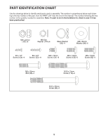
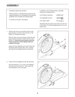
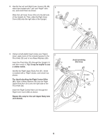
ASSEMBLY •• Assembly requires two persons. •• Place all parts in a cleared area and remove the packing materials. Do not dispose of the packing materials until you nish all assembly steps. •• To identify small parts, see page 5. •• In addition to the included tool(s), assembly requires the following tools: one Phillips screwdriver one adjustable wrench one rubber mallet Assembly may be easier if you have your own set of wrenches. To avoid damaging parts, do not use power tools. 1. Remove the screws (not shown) and the shipping bracket (not shown) from the front of the 1 Frame (1). Discard the screws. With the help of a second person, place the shipping bracket (not shown) under the front of the Frame (1). Have the second person hold the Frame to prevent it from tipping while you complete this step. Attach the Front Stabilizer (6) to the Frame with two M10 x 90mm Screws (84). Then, remove and discard the shipping bracket (not shown). 6 84 1 2. Orient the Front Stabilizer Cover (8) as shown. 2 Press the Mounts (117) on the Front Stabilizer Cover (8) into the Frame (1). Then, press the Front Stabilizer Cover into place. 8 117 1 6
-
 1
1 -
 2
2 -
 3
3 -
 4
4 -
 5
5 -
 6
6 -
 7
7 -
 8
8 -
 9
9 -
 10
10 -
 11
11 -
 12
12 -
13
-
14
-
15
-
16
-
17
-
18
-
19
-
20
-
21
-
22
-
23
-
24
-
25
-
26
-
27
-
28
-
29
-
30
-
31
-
32
-
33
-
34
-
35
-
36
 |
 |
