NordicTrack Smart Terrain 12.0 Elliptical English Manual - Page 7
Attach the Rear Stabilizer 5 to the Frame 1
 |
View all NordicTrack Smart Terrain 12.0 Elliptical manuals
Add to My Manuals
Save this manual to your list of manuals |
Page 7 highlights
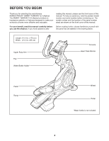
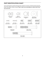
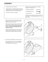
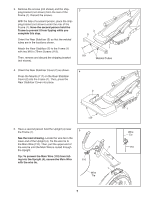
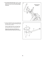
3. Remove the screws (not shown) and the shipping bracket (not shown) from the rear of the Frame (1). Discard the screws. With the help of a second person, place the shipping bracket (not shown) under the rear of the Frame (1). Have the second person hold the Frame to prevent it from tipping while you complete this step. Orient the Rear Stabilizer (5) so that the welded tubes are in the locations shown. Attach the Rear Stabilizer (5) to the Frame (1) with two M10 x 75mm Screws (119). Then, remove and discard the shipping bracket (not shown). 3 3 5 1 119 Welded Tubes 4. Orient the Rear Stabilizer Cover (2) as shown. 4 Press the Mounts (117) on the Rear Stabilizer Cover (2) into the Frame (1). Then, press the Rear Stabilizer Cover into place. 2 117 5. Have a second person hold the Upright (4) near the Frame (1). 5 See the inset drawing. Locate the wire tie in the lower end of the Upright (4). Tie the wire tie to the Main Wire (110). Then, pull the upper end of the wire tie until the Main Wire is routed through 4 the Upright. Tip: To prevent the Main Wire (110) from fall- ing into the Upright (4), secure the Main Wire 110 with the wire tie. 1 Wire Tie 7 1 Wire Tie 110
-
 1
1 -
 2
2 -
 3
3 -
 4
4 -
 5
5 -
 6
6 -
 7
7 -
 8
8 -
 9
9 -
 10
10 -
 11
11 -
 12
12 -
13
-
14
-
15
-
16
-
17
-
18
-
19
-
20
-
21
-
22
-
23
-
24
-
25
-
26
-
27
-
28
-
29
-
30
-
31
-
32
-
33
-
34
-
35
-
36
 |
 |
