Oki ML421 Maintenance Manual - Page 63
Space Motor, Guide Roller Assy
 |
View all Oki ML421 manuals
Add to My Manuals
Save this manual to your list of manuals |
Page 63 highlights
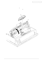
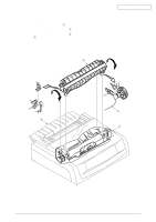
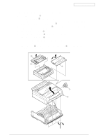
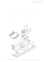
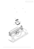
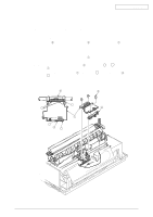
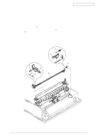
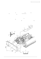
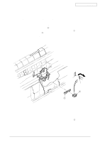
Oki Data CONFIDENTIAL 3.3.7 Space Motor, Guide Roller Assy (1) Remove the printhead (see 3.3.1). (2) Remove the upper cover (see 3.3.4 (1) - (5)). (3) Remove the gear case Assy (see 3.3.5). (4) Remove the PC connector (see 3.3.6). (5) Remove screw 2, then the guide roller Assy 3 from the space motor 1. (6) To install, follow the removal steps in the reverse order. Notes on installation: (1) Do not touch the terminals of space motor 1. Also, take care to avoid dust or foreign matters. (2) When installing the guide roller Assy 3, push portions A and B against the space motor 1. (3) When installing the space motor 1, align the face C with carriage frame 4 and push portion D against the frame. (4) After installation, check and adjust the gap between platen and printhead (see 4-1). 4 2 C D 3 1 B 3A 42113901 Rev.2 63 /
-
 1
1 -
2
-
3
-
4
-
5
-
6
-
7
-
8
-
9
-
10
-
11
-
12
-
13
-
14
-
15
-
16
-
17
-
18
-
19
-
20
-
21
-
22
-
23
-
24
-
25
-
26
-
27
-
28
-
29
-
30
-
31
-
32
-
33
-
34
-
35
-
36
-
37
-
38
-
39
-
40
-
41
-
42
-
43
-
44
-
45
-
46
-
47
-
48
-
49
-
50
-
51
-
52
-
53
-
54
-
55
-
56
-
57
-
 58
58 -
 59
59 -
 60
60 -
 61
61 -
 62
62 -
 63
63 -
 64
64 -
 65
65 -
 66
66 -
 67
67 -
 68
68 -
69
-
70
-
71
-
72
-
73
-
74
-
75
-
76
-
77
-
78
-
79
-
80
-
81
-
82
-
83
-
84
-
85
-
86
-
87
-
88
-
89
-
90
-
91
-
92
-
93
-
94
-
95
-
96
-
97
-
98
-
99
-
100
-
101
-
102
-
103
-
104
-
105
-
106
-
107
-
108
-
109
-
110
-
111
-
112
-
113
-
114
-
115
-
116
-
117
-
118
-
119
-
120
-
121
-
122
-
123
-
124
-
125
-
126
-
127
-
128
-
129
-
130
-
131
-
132
-
133
 |
 |
