Onkyo HT-S490 Owner Manual - Page 10
Rear panel facilities
 |
View all Onkyo HT-S490 manuals
Add to My Manuals
Save this manual to your list of manuals |
Page 10 highlights
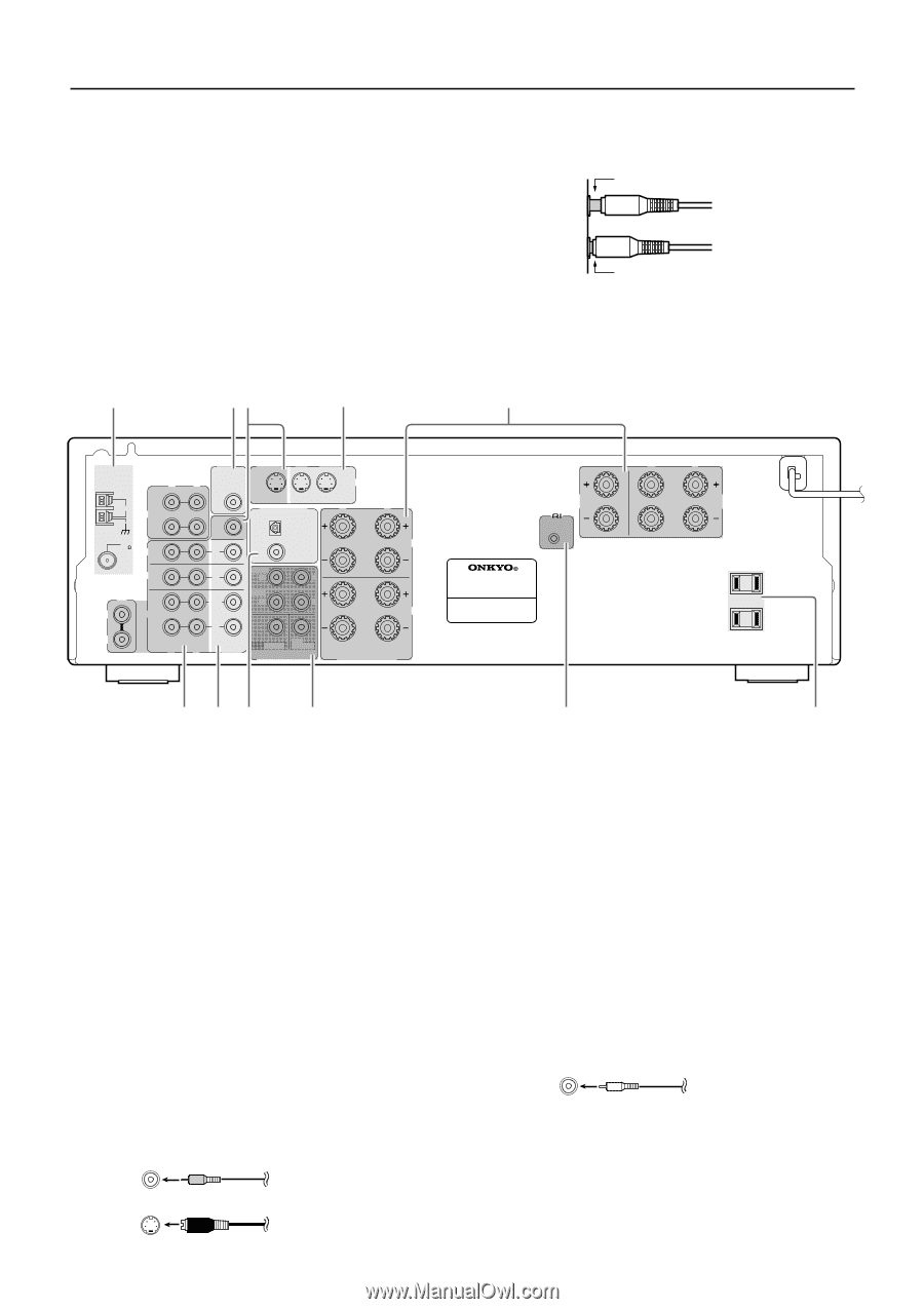
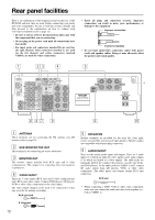
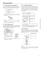
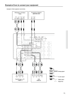
Rear panel facilities Here is an explanation of the terminals found on the rear of the HT-R490 and how they are used. Before connecting your audio and video components, be sure to read this section carefully and then proceed to the explanations on how to connect each individual component (refer to page 12). • Be sure to always refer to the instructions that came with the component that you are connecting. • Do not plug in the power cord until all connections have been made. • For input jacks, red connectors (marked R) are used for the right channel, white connectors (marked L) are used for the left channel, and yellow connectors (marked VIDEO) are used for video connections. • Insert all plugs and connectors securely. Improper connections can result in noise, poor performance, or damage to the equipment. Improper connection Inserted completely • Do not bind audio/video connection cables with power cords and speaker cables. Doing so may adversely effect the picture and sound quality. 1 23 4 5 ANTENNA R OUT AM TAPE IN FM 75 DVD VIDEO 1 CD L VIDEO 2 R R SUB MONITOR DVD VIDEO 1 WOOFER OUT PRE OUT L S VIDEO IN IN DIGITAL INPUT R L MONITOR OUT OPTICAL A IN COAXIAL FRONT IN R L SURR OUT R L IN L VIDEO SUB CENTER WOOFER MULTI CHANNEL INPUT B R L FRONT SPEAKERS CENTER SPEAKER REMOTE CONTROL AV RECEIVER MODEL NO. HT-R490 6 47 8 9 R L SURROUND SPEAKERS AC OUTLETS AC 120V 60Hz SWITCHED TOTAL 120W 1A MAX. p 1 ANTENNA These terminals are for connecting the FM antenna and AM antenna (refer to page 18). 2 SUB WOOFER PRE OUT This terminal is for connecting an active subwoofer. 3 MONITOR OUT The monitor output includes both RCA type and S video configurations. This output is for connecting television monitors or projectors. 4 VIDEO IN/OUT There are 3 video inputs (RCA type and S video configurations) and 1 RCA type video output. Connect DVD players, LD players, VCRs or other video components to the video inputs. The video output channel can be used to be connected to video tape recorder for making recordings. RCA type jack 5 SPEAKERS Speaker terminals are provided for the front left, front right, center, surround left and surround right speakers. Speaker outputs are compatible with banana plug connectors. 6 AUDIO IN/OUT These are the analog audio inputs and outputs. There are 5 audio inputs (3 of which are linked to video inputs) and 2 audio outputs (1 of which are linked to a video output). The audio jacks are nominally labeled for compact disc players, cassette tape decks, and DVD players. To the audio jacks for VIDEO 1 and 2 connect the audio output from LD players, VCRs or other video components. The audio inputs and outputs require RCA type connectors. RCA type • When connecting a DVD, VCR or other video component, make sure you connect the audio and video leads together (i.e., both to VIDEO 1). S Video jack 10
-
 1
1 -
2
-
3
-
4
-
 5
5 -
 6
6 -
 7
7 -
 8
8 -
 9
9 -
 10
10 -
 11
11 -
 12
12 -
 13
13 -
 14
14 -
 15
15 -
16
-
17
-
18
-
19
-
20
-
21
-
22
-
23
-
24
-
25
-
26
-
27
-
28
-
29
-
30
-
31
-
32
-
33
-
34
-
35
-
36
 |
 |