Optoma H50 User Manual - Page 11
Installation - digital projector
 |
View all Optoma H50 manuals
Add to My Manuals
Save this manual to your list of manuals |
Page 11 highlights
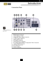
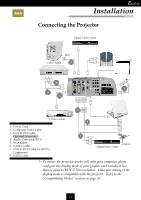
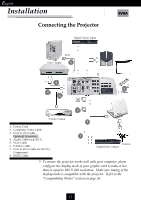
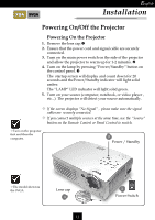
XGA SVGA English Installation Connecting the Projector Digital Tuner Output RS232 Video Output 8 RS232 INPUT OUTPUT AUDIO AUDIO AUDIO 4 DVI COMPUTER +12V RELAY AUDIO 1 VIDEO 2 S-VIDEO 6 3 RGB S-Video Output 1. Power Cord 2. Composite Video Cable 3. D-15 to DVI Cable Optional Accessory: 4. Audio Cable Jack/RCA 5. VGA Cable 6. S-Video Cable 7. D-15 to RCA Cable for HDTV/ Component 8. RS232 Cable 5 7 Antenna Digital Tuner Output v To ensure the projector works well with your computer, please configure the display mode of your graphic card to make it less than or equal to 1024 X 768 resolution. Make sure timing of the display mode is compatible with the projector. Refer to the “Compatibility Modes” section on page 35. 11
-
 1
1 -
2
-
3
-
4
-
5
-
 6
6 -
 7
7 -
 8
8 -
 9
9 -
 10
10 -
 11
11 -
 12
12 -
 13
13 -
 14
14 -
 15
15 -
 16
16 -
17
-
18
-
19
-
20
-
21
-
22
-
23
-
24
-
25
-
26
-
27
-
28
-
29
-
30
-
31
-
32
-
33
-
34
-
35
-
36
 |
 |

11
E
nglish
XGA
Connecting the Projector
v
To ensure the projector works well with your computer, please
configure the display mode of your graphic card to make it less
than or equal to 1024 X 768 resolution.
Make sure timing of the
display mode is compatible with the projector.
Refer to the
±Compatibility Modes² section on page 35.
S-Video Output
Video Output
8
5
6
4
7
3
Digital Tuner Output
Digital Tuner Output
Antenna
RS232
AUDIO
VIDEO
S-VIDEO
AUDIO
AUDIO
AUDIO
DVI
COMPUTER
+12V RELAY
RGB
RS232
2
INPUT
OUTPUT
1.
Power Cord
2.
Composite Video Cable
3.
D-15 to DVI Cable
Optional Accessory:
4.
Audio Cable Jack/RCA
5.
VGA Cable
6.
S-Video Cable
7.
D-15 to RCA Cable for HDTV/
Component
8.
RS232 Cable
Installation
1