Oreck Air 6 Owners Guide - Page 17
Rotating Element Warning - air 7 fan grommet
 |
View all Oreck Air 6 manuals
Add to My Manuals
Save this manual to your list of manuals |
Page 17 highlights
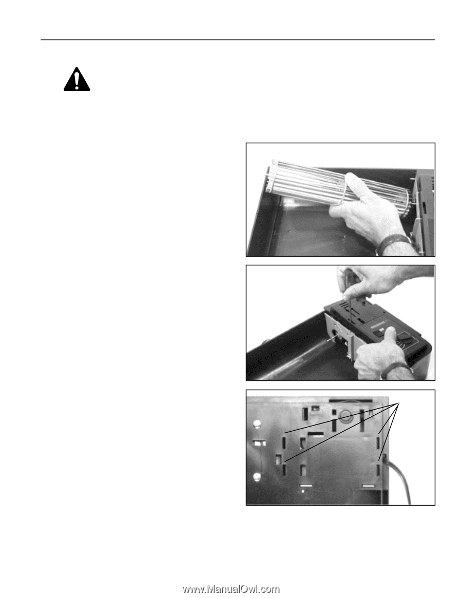
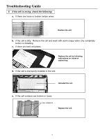
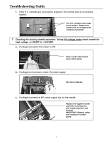
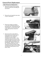
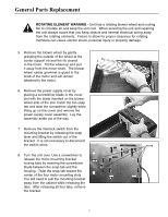
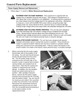
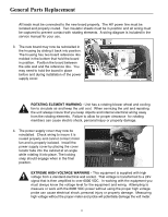
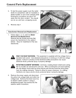
General Parts Replacement ROTATING ELEMENT WARNING - Unit has a rotating blower wheel and cooling fan to circulate air and keep the unit cool. When servicing the unit and repairing the unit always insure that you keep objects and internal electrical wiring away from the rotating elements. Failure to allow for proper clearance for rotating members can cause electric shock, personal injury or property damage. 5. Remove the blower wheel by gently grasping the outside of the wheel at the center support rib and the rib closest to the motor. Tilt the wheel up and pull it away from the motor shaft. The blower wheel rubber grommet is glued to the shaft of the motor and will remain attached to the motor. 6. Remove the power supply cover by placing a screwdriver blade in the cover slot with the blade inserted on the blower wheel side of the slot. Catch the tan snap tab and twist the screwdriver slightly while lifting up on the cover and remove the power supply cover assembly. Lay the assembly aside out of the way. 7. Remove the interlock switch from the mounting bracket by releasing the snap lever and lifting the switch out of the bracket. It is not necessary to disconnect the switch wires. SLOTS 8. Turn the unit over. Use a screwdriver to release the motor mounting bracket locking tabs by inserting the screwdriver blade between the snap tab and the housing. Twist the snap tab toward the center of the four motor mounting slots. You will need to pull the mounting bracket away from the cabinet while releasing the tabs. After releasing all four tabs, remove the bracket. 17
-
 1
1 -
2
-
3
-
4
-
5
-
6
-
7
-
8
-
9
-
10
-
11
-
 12
12 -
 13
13 -
 14
14 -
 15
15 -
 16
16 -
 17
17 -
 18
18 -
 19
19 -
 20
20 -
 21
21 -
 22
22 -
23
-
24
-
25
-
26
-
27
-
28
 |
 |