Oreck Air 6 Owners Guide - Page 20
Rotating Element Warning, Extreme High Voltage Warning - air 7 manual
 |
View all Oreck Air 6 manuals
Add to My Manuals
Save this manual to your list of manuals |
Page 20 highlights
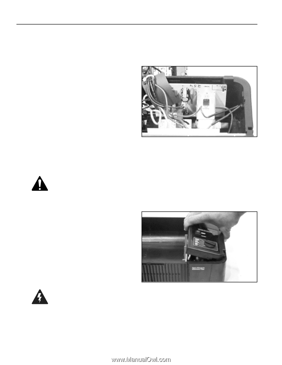
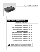
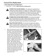
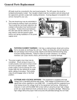
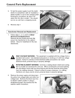
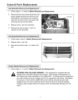
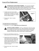
General Parts Replacement All leads must be connected to the new board properly. The HV power line must be isolated and properly routed. Two insulator sheets must be in position and all wiring must be captured to prevent contact with rotating elements. A wiring diagram is included in the service manual for your use. 3. The new board may now be reinstalled in the housing by sliding it back into position. The housing has two board reference ribs molded in the bottom that hold the board in position. Position the board between the side wall and the reference ribs. You may need to hold the board in place before and during installation of the power supply cover. ROTATING ELEMENT WARNING - Unit has a rotating blower wheel and cooling fan to circulate air and keep the unit cool. When servicing the unit and repairing the unit always insure that you keep objects and internal electrical wiring away from the rotating elements. Failure to allow for proper clearance for rotating members can cause electric shock, personal injury or property damage. 4. The power supply cover may now be reinstalled. Check wiring to insure it is routed properly and cannot contact motor fan and is properly isolated. Install the power supply cover by placing the cover locator tabs into the cabinet at an angle while rotating it into place. The locking snap should engage when in the final position. EXTREME HIGH VOLTAGE WARNING - This equipment is supplied with high voltage from a standard electrical wall socket. That voltage is transformed to a 24V signal that is then amplified to over 6000 VDC. In working with the equipment you must always know the voltage level for the equipment and wiring. Attempting to measure or work with the 6000 VDC power without using the proper high voltage probe can cause electrical shock, personal injury or property damage. Measuring high voltage without the proper meter and probe will potentially damage the volt meter. 20
-
 1
1 -
2
-
3
-
4
-
5
-
6
-
7
-
8
-
9
-
10
-
11
-
12
-
13
-
14
-
 15
15 -
 16
16 -
 17
17 -
 18
18 -
 19
19 -
 20
20 -
 21
21 -
 22
22 -
 23
23 -
 24
24 -
 25
25 -
26
-
27
-
28
 |
 |