Oregon Scientific WMR968 User Manual - Page 3
Operation - replacement sensors
 |
View all Oregon Scientific WMR968 manuals
Add to My Manuals
Save this manual to your list of manuals |
Page 3 highlights
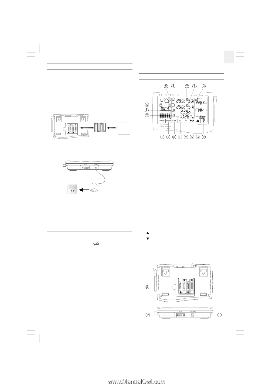
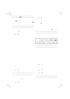
GB THE MAIN UNIT The main unit gives you all the readings and controls. It should be placed indoors. The main unit is powered up by the 12V AC adapter. To install it, 1. Position the main unit and other units within effective range (109 yards). 2. Insert four UM3 or "AA"-sized alkaline batteries for backup purpose. SECTION 3 OPERATION THE MAIN UNIT 3. Mount the main unit safely in place. Or use its table stand to place it on a flat surface. 4. Connect the AC power adapter to the main unit and a wall socket. 5. Press the [RESET] button on the main unit to initiate operation. The main unit will start searching for signals for about four minutes. Upon successful reception, the readings will be displayed. The main unit will update the readings at regular intervals. Note: That if the main unit is operating solely on battery power, the EL backlight and RS232 connection will be disabled. LOW-BATTERY WARNING There are low-battery indicators [ ] for the main unit, rain gauge, baro-thermo-hygrometer, thermo-hygrometer and optional remote thermo and thermo-hygro sensors. Replace the batteries when the respective indicators light up. Note: The readings collected from the thermo-hygrometer and any optional remote thermo and thermo-hygro sensors share the same display window. The "OUT" and remote channel will share the same low-battery indicator. When the battery level of the thermohygrometer is low, the low-battery indicator will turn on. If it is one of the optional remote sensors, the low-battery indicator will blink. To locate the channel in question, press the window to scan through all available devices. The low-battery indicator will stop blinking if the battery level is low for that one. A. WEATHER FORECAST AND BAROMETRIC READING WINDOW B. INDOOR TEMPERATURE WINDOW C. INDOOR HUMIDITY WINDOW D. OUTDOOR/CHANNEL TEMPERATURE WINDOW E. OUTDOOR/CHANNEL HUMIDITY WINDOW F. RAINFALL WINDOW G. CALENDAR CLOCK AND DAILY ALARM WINDOW H. WIND SPEED AND DIRECTION WINDOW I. CHANNEL BUTTON J. MEMORY BUTTON K. ALARM BUTTON L. SET BUTTON M. UNIT BUTTON N. ALARM ON/OFF BUTTON O. [U] BUTTON P. [V] BUTTON Q. [RESET] BUTTON R. RS232 SERIAL PORT S. DC 12V JACK 928N-USE.p65 3 3 08/10/2001, 12:20 PM
-
 1
1 -
 2
2 -
 3
3 -
 4
4 -
 5
5 -
 6
6 -
 7
7 -
 8
8 -
 9
9
 |
 |