Panamax M7500-PRO Manual - Page 9
Telephone Protection, To protect a telephone jack, Please Note, EQUIP, AC Surge Protection, Patent
 |
UPC - 050616008068
View all Panamax M7500-PRO manuals
Add to My Manuals
Save this manual to your list of manuals |
Page 9 highlights
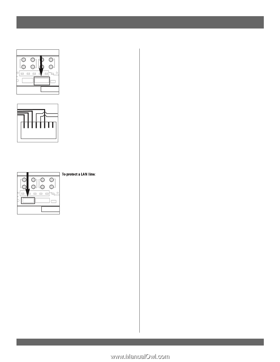
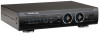
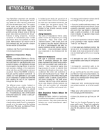
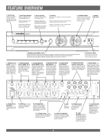
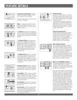
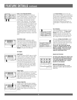
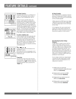
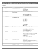
FEATURE DETAILS (continued) GH CURRENT CIRCUIT BREAKER BANKS 3 AND 4 1 UNIVERSAL COAX 2 PROTECTION UNIVERSAL 3 COAX PROTECTION 4 HC 1 SWITCHED RECEIVER HC 2 SWITCHED ALWAYS ON DELAY ALWAYS ON DELAY ALWAYS ON DELAY ALWAYS ON DELAY ALWAYS ON DELAY SWITCH SETTINGS TRIGGER INPUT OUTPUT 3-24VDC 12V/400mA BANK 2 BANK 3 LAN LINE IN LAN TO EQUIP BANK 4 PHONE LINE IN 5 HC 1 PHONE LINE TO EQUIP 1 5 HC 2 PHONE LINE TO EQUIP 2 IN OUT OUT CUSTOM SETTINGS USB LIGHT 5VDC/100mA P MAX LAN TEL COMMUNICATION INTERFACE Telephone Protection: This unit provides protection to one telephone Line In (RJ-11), and incorporates a built-in splitter to Equipment 1 (RJ-11) and Equipment 2 (RJ-11). Satellite TV receivers and DVR's (digital video recorders) require telephone line connections for subscription services. The MAX 7500-Pro provides surge protection for this line. The circuitry utilizes auto-resetting PTCRs and solid-state SIDACtors for reliability and unsurpassed protection. The clamping level of the MAX 7500-Pro's telephone protector is 260 volts. This will allow typical ring voltage (90130VAC) and operating battery voltage (-48DC) to pass through the circuit and still protect the modem in your satellite receiver or DVR from damage. 1 2 3 4 5 6 7 8 RJ-45 To protect a telephone jack: Connect a telephone cable from the wall jack outlet to the Line In (RJ-11) jack on the MAX 7500-Pro, then connect a second telephone cable from either the Equipment 1 (RJ-11) or Equipment 2 (RJ-11) jack on the MAX 7500-Pro to the equipment's phone jack. An RJ-11 connector with a minimum of 26 AWG conductors needs to be used when connecting to the telephone jacks. 1 UNIVERSAL COAX 2 PROTECTION UNIVERSAL 3 COAX PROTECTION 4 ALWAYS ON DELAY ALWAYS ON DELAY ALWAYS ON DELAY ALWAYS ON DELAY ALWAYS ON DELAY SWITCH SETTINGS TRIGGER OUTPUT 12V/400mA BANK 2 BANK 3 LAN LINE IN LAN TO EQUIP BANK 4 PHONE LINE IN IN OUT 5 HC 1 PHONE LINE TO EQUIP 1 5 HC 2 PHONE LINE TO EQUIP 2 CUSTOM SETTINGS USB LIGHT 5VDC/100mA To protect a LAN line: Connect a network cable from the wall jack to the MAX 7500-Pro Line In (RJ-45) jack, then connect a second cable from the Equipment (RJ-45) jack on the MAX 7500-Pro to the network device jack. Please Note: The protection circuitry will not work if the phone lines are reversed. The incoming phone cable must be connected to the "LINE" jack and the cable to the audio/video equipment must be connected to the "EQUIP" jack. 7 AC Surge Protection: When the MAX 7500-Pro is subjected to a high voltage surge, its voltage output is limited to a safe level and the high levels of surge current are diverted away from the connected equipment. • When subjected to a 6,000V (open circuit voltage) / 500A (short circuit current) surge, the MAX 7500Pro limits its voltage output to less than 330V peak, UL's best rating. • If the magnitude of the surge is greater than the capacity of the surge protection components, the MAX 7500-Pro's Protect or Disconnect Circuitry will disconnect your equipment in order to protect it. Patent Pending Over/Under Voltage Protection: The MAX 7500-Pro constantly monitors the AC line voltage for unsafe voltage conditions such as prolonged over voltages and under voltages (brownouts). These unsafe conditions pose a very dangerous threat to all electronic equipment within the home. If the MAX 7500-Pro senses an unsafe power condition, it will automatically disconnect your equipment from the power to protect equipment from damage. Once the voltage returns to a safe level, the MAX 7500-Pro will automatically reconnect the power. If the line voltage exceeds the over voltage threshold or falls below the under voltage threshold, the MAX 7500-Pro will perform the following tasks until line voltage returns to a safe level: 1. Voltage reaches an unsafe high level and the (Automatic Voltage Monitoring) AVM Circuitry disconnects. 2. Voltage reaches a safe level and AVM Circuitry automatically reconnects. 3. Voltage reaches an unsafe low level and AVM Circuitry disconnects. 4. Voltage reaches a safe level and AVM Circuitry automatically reconnects.
-
 1
1 -
2
-
3
-
 4
4 -
 5
5 -
 6
6 -
 7
7 -
 8
8 -
 9
9 -
 10
10 -
 11
11 -
 12
12 -
 13
13 -
 14
14 -
15
-
16
-
17
 |
 |