Panasonic BL-C140A Installation Guide - Page 7
Camera Diagrams - bl c140
 |
UPC - 037988845415
View all Panasonic BL-C140A manuals
Add to My Manuals
Save this manual to your list of manuals |
Page 7 highlights
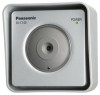
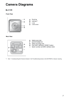
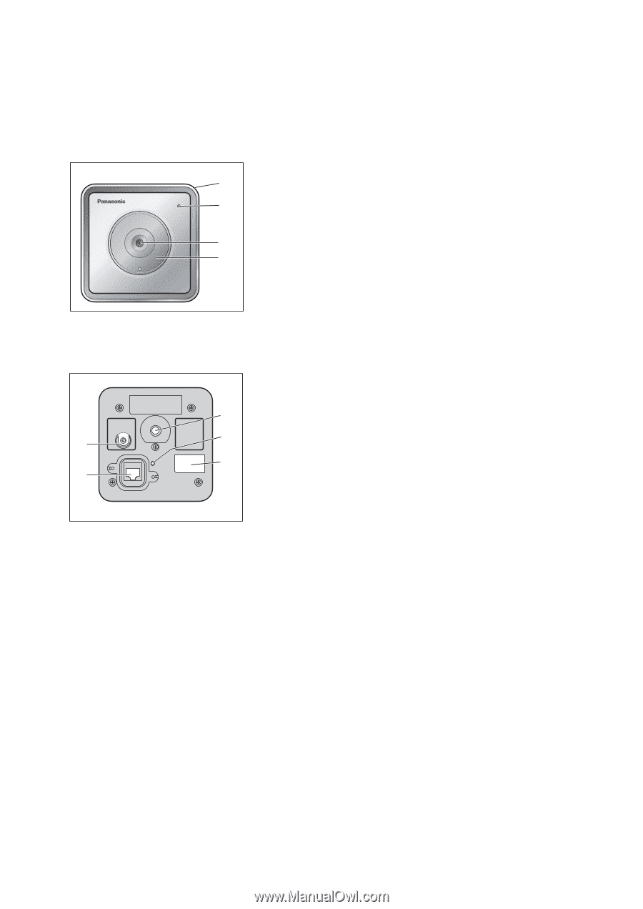
Camera Diagrams BL-C140 Front View A A Housing B B Indicator*1 C Lens D Lens cover C D Rear View E F E Safety wire hole F DATA/POWER IN G G Stand mounting hole H FACTORY DEFAULT RESET button H I Serial number and MAC address label I *1 See 1.1 Understanding the Camera Indicator in the Troubleshooting Guide on the CD-ROM for indicator meaning. 7
-
 1
1 -
 2
2 -
 3
3 -
 4
4 -
 5
5 -
 6
6 -
 7
7 -
 8
8 -
 9
9 -
 10
10 -
 11
11 -
 12
12 -
13
-
14
-
15
-
16
-
17
-
18
-
19
-
20
-
21
-
22
-
23
-
24
-
25
-
26
-
27
-
28
-
29
-
30
-
31
-
32
 |
 |
7
Camera Diagrams
BL-C140
*1
See 1.1 Understanding the Camera Indicator in the Troubleshooting Guide on the CD-ROM for indicator meaning.
Front View
A
B
C
D
Housing
Indicator
*1
Lens
Lens cover
Rear View
E
F
G
H
I
Safety wire hole
DATA/POWER IN
Stand mounting hole
FACTORY DEFAULT RESET button
Serial number and MAC address label
B
A
D
C
E
G
H
I
F