Panasonic BT300 Blu-ray Disc Home Theater Sound System - Page 6
Control reference guide (main unit - setup
 |
UPC - 037988983520
View all Panasonic BT300 manuals
Add to My Manuals
Save this manual to your list of manuals |
Page 6 highlights
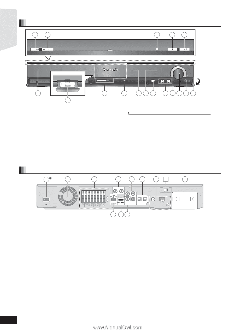
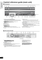
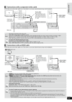
Getting started Control reference guide (main unit) Front panel 1 2 3 4 5 POWER OPEN CLOSE Dock for iPod SMART SETUP Dock for iPod SD CARD SURROUND OUTPUT SETUP MIC SELECTOR TUNE VOLUME Pull open 6 8 7 1 Standby/on switch (POWER Í/I) (> 19) Press to switch the unit from on to standby mode or vice versa. In standby mode, the unit is still consuming a small amount of power. 2 Open or close the disc tray (> 19) 3 [BT300] \BT303\ [BT200] : SMART SETUP button (> 15) [BT203] : EASY SETUP button (> 15) 4 Stop (> 19) 5 Start play (> 19) 6 Disc tray (> 19) 7 Connect iPod (> 30) 8 SD card slot (> 19) 9 [BT300] \BT303\ [BT200] : Connect Auto speaker setup microphone (> 15) : The indicator lights when there is surround sound effect. (> 18) ; Display 9 10 11 12 13 14 15 16 17 < Select the source BD/DVD ) SD )IPOD ) FM )AM )AUX )D-IN 1 )D-IN 2 "SD" on the unit's display is not displayed when the SD card is not in the SD card slot. = Skip or slow-search play (> 20) / Select the radio stations (> 26) > Volume indicator ≥It is possible to set the indicator to turn on/off. (> 38, FL Display) ? Adjust the volume of the main unit (> 19) ≥When pulled hard, the volume knob may come off. To prevent children from swallowing the volume knob, do not pull off the volume knob. @ Connect headphones (not included) (> 19) A Remote control signal sensor Rear panel terminals 1 2 3 4 56 7 12 8 AC IN SPEAKERS R AUX(TV) L ( 6 5 21 4387 3Ω SUB- 3Ω R 3Ω L R 3Ω L R 3Ω L WOOFER CENTER FRONT SURROUND SURROUND BACK + Y PB OPTICAL ) AV OUT PR 2(STB) 1(TV) VIDEO COMPONENT OUT VIDEO OUT DIGITAL IN 75Ω FM ANT VOLT ADJ 110 220 127V 240V LOOP EXT AM ANT LOOP ANT GND PUSH DIGITAL TRADNIGSIMTAITLTER TRANSMITTER PUSH 9 1 AC IN T terminal (> 14) [For[units[with[PX[printed[on[the[packaging[ * The terminal is not polarized. 2 Cooling fan 3 SPEAKERS terminal (> 9) 4 AUX(TV) terminal (> 10, 11) This terminal can also be used for equipment other than the TV. 5 COMPONENT VIDEO OUT terminal (> 11) 6 OPTICAL DIGITAL IN terminals Terminal 1(TV) is designated for connection with the TV (> 10, 11) Terminal 2(STB) can be used with equipment other than the STB (> 12) 10 11 7 Radio antenna terminals (> 13) 8 Digital transmitter dock (> 45) 9 LAN port (> 14) : HDMI AV OUT terminal (> 11) ; VIDEO OUT terminal (> 10) [For[units[with[PX[printed[on[the[packaging[ qR AC Voltage selector (> 14) RQT9508 6
-
 1
1 -
 2
2 -
 3
3 -
 4
4 -
 5
5 -
 6
6 -
 7
7 -
 8
8 -
 9
9 -
 10
10 -
 11
11 -
 12
12 -
13
-
14
-
15
-
16
-
17
-
18
-
19
-
20
-
21
-
22
-
23
-
24
-
25
-
26
-
27
-
28
-
29
-
30
-
31
-
32
-
33
-
34
-
35
-
36
-
37
-
38
-
39
-
40
-
41
-
42
-
43
-
44
-
45
-
46
-
47
-
48
-
49
-
50
-
51
-
52
-
53
-
54
-
55
-
56
-
57
-
58
-
59
-
60
 |
 |