Panasonic CT36SX12F CT32SX12 User Guide - Page 8
Optional Equipment Connections, Vcr Connection, Front Control Panel - manual
 |
View all Panasonic CT36SX12F manuals
Add to My Manuals
Save this manual to your list of manuals |
Page 8 highlights
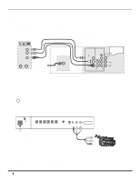
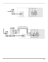
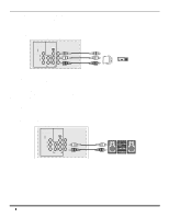
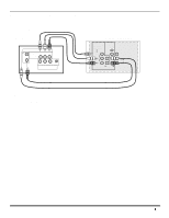
OPTIONAL EQUIPMENT CONNECTIONS Optional Equipment Connections VCR Connection VCRs, video disc players, video game equipment, and DSS equipment can also be connected to the video inputs. See the optional equipment manual for more information. Note: Input 1 is a dual-purpose input. It is primarily intended for connection with 480i devices such as a DVD player using the Y PB PR component video jacks and Audio L & R jacks. However, it can also be connected to conventional composite video sources such as a VCR, using only the Y/Video jack and Audio L & R jacks. The on-screen label will display Component or Video 1 depending on which source is connected. VCR VIDEO OUT L AUDIO OUT R ANT OUT ANT IN Incoming Cable ANT CABLES NOT SUPPLIED TERMINALS ON BACK OF THE TV INPUT 1 COMPONENT VIDEO INPUTS VIDEO/Y INPUT 2 S-VIDEO PROG OUT Use either the S-Video or Video connection. VIDEO PB L PR R L L TO AUDIO AMP R R AUDIO Note: The remote control must be programmed with supplied codes to operate the VCR. Procedure 1. Connect equipment as shown to rear Audio/Video input jacks. 2. Select the Video mode by pressing TV/VIDEO button. 3. Operate optional equipment as instructed in equipment manual. Front Control Panel TV/VIDEO Press to select VIDEO 3 input mode. Note: The front control panel located behind the customer control door can be used to access menus and switch video mode when the remote control is not available. ON/OFF INDICATOR POW ER Note: The ON/OFF indicator LED (red) will be lit when set is on. VOLUME CHANNEL ACTION TV/VIDEO HPJ S-VIDEO VIDEO L-AUDIO-R INPUT 3 POWER ON/OFF Note: The S-VIDEO connection provides higher quality picture. It overrides VIDEO 3 connections. Use INPUT 3, AUDIO L and R with S-VIDEO connection. CAMCORDER A second VCR, Camcorder, a video disc player, video game equipment or DSS equipment can also be connected to the video inputs. See the optional equipment manual for details. Procedure 1. Connect equipment to front Audio/Video input jacks. 2. Press TV/VIDEO button to select VIDEO 3 input mode. 3. Operate optional equipment as instructed in equipment manual. 6
-
 1
1 -
2
-
 3
3 -
 4
4 -
 5
5 -
 6
6 -
 7
7 -
 8
8 -
 9
9 -
 10
10 -
 11
11 -
 12
12 -
 13
13 -
14
-
15
-
16
-
17
-
18
-
19
-
20
-
21
-
22
-
23
-
24
-
25
-
26
-
27
-
28
-
29
-
30
-
31
-
32
-
33
-
34
-
35
-
36
-
37
-
38
-
39
-
40
-
41
-
42
-
43
-
44
-
45
-
46
-
47
-
48
-
49
-
50
-
51
-
52
-
53
-
54
-
55
-
56
-
57
-
58
-
59
-
60
-
61
-
62
-
63
-
64
-
65
-
66
-
67
-
68
-
69
-
70
-
71
-
72
 |
 |
