Panasonic HPX300 Operating Instructions - Page 15
Parts and Their Functions, Power Supply and Accessory Mounting
 |
UPC - 791871304297
View all Panasonic HPX300 manuals
Add to My Manuals
Save this manual to your list of manuals |
Page 15 highlights
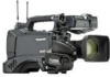
Chapter 2 Parts and Their Functions Power Supply and Accessory Mounting Section 17 6 13 2 16 6 5 14 8 Chapter 2 Parts and their Functions 1 4 3 15 10 12 11 7 9 1 POWER switch Use to turn the power on and off. 2 Battery holder A battery from Anton/Bauer is mounted here. For details, refer to [Mounting the Battery and Setting the Battery Type] (page 86). 3 DC IN (external power input) socket (XLR, 4P) Connect this camera to an external DC power supply. For details, refer to [Use of the external DC power supply] (page 88). 4 BREAKER switch This switch is located on the camera base. When an excessive amount of current is fed through the video camera recorder, due to a malfunction, the breaker automatically turns off the power to protect the device. Press this button after conducting an internal inspection or repair. The camera will power up if it is working normally. 5 Light shoe A video light or similar accessory can be attached here. (Size of holes for securing screws) • 1/4-20UNC (6 mm or shorter screws) 6 Shoulder strap fittings The shoulder strap is attached here. For details, refer to [Attaching the Shoulder Strap] (page 97). 7 Lens mount (1/3-bayonet mount) The lens is attached here. For details, refer to [Mounting the Lens] (page 89). 8 Lens lever Tighten this lever to lock the lens to the lens mount. For details, refer to [Mounting the Lens] (page 89). 9 Mount cap To remove the cap, raise the lens lever. Replace the cap when a lens is not mounted. 10 Lens cable/microphone cable clamp This clamp secures the lens and microphone cables. For details, refer to [Mounting the Lens] (page 89). 11 Tripod mount To mount the camera on a tripod, attach the optional tripod adapter (SHAN-TM700) here. For details, refer to [Mounting the Camera on a Tripod] (page 97). 12 Lens jack (12-pin) The lens connection cord is connected here. For a detailed description of your lens, refer to the manufacturer's instruction manual. 13 Battery release lever Pull down the release lever to release the battery. 14 Viewfinder left-right positioning ring For details, see [Adjusting Right and Left Viewfinder Position] (page 78). 15 Light control switch For details, refer to [Power Supply] (page 86). 16 Cable holder Used to secure the light and microphone cables. 17 Accessory mounting hole Accessories can be attached here. Do not use this hole for purposes other than attaching accessories. (Size of holes for securing screws) • 1/4-20UNC (10 mm or shorter screws) • 3/8-16UNC (10 mm or shorter screws) 15
-
 1
1 -
2
-
3
-
4
-
5
-
6
-
7
-
8
-
9
-
 10
10 -
 11
11 -
 12
12 -
 13
13 -
 14
14 -
 15
15 -
 16
16 -
 17
17 -
 18
18 -
 19
19 -
 20
20 -
21
-
22
-
23
-
24
-
25
-
26
-
27
-
28
-
29
-
30
-
31
-
32
-
33
-
34
-
35
-
36
-
37
-
38
-
39
-
40
-
41
-
42
-
43
-
44
-
45
-
46
-
47
-
48
-
49
-
50
-
51
-
52
-
53
-
54
-
55
-
56
-
57
-
58
-
59
-
60
-
61
-
62
-
63
-
64
-
65
-
66
-
67
-
68
-
69
-
70
-
71
-
72
-
73
-
74
-
75
-
76
-
77
-
78
-
79
-
80
-
81
-
82
-
83
-
84
-
85
-
86
-
87
-
88
-
89
-
90
-
91
-
92
-
93
-
94
-
95
-
96
-
97
-
98
-
99
-
100
-
101
-
102
-
103
-
104
-
105
-
106
-
107
-
108
-
109
-
110
-
111
-
112
-
113
-
114
-
115
-
116
-
117
-
118
-
119
-
120
-
121
-
122
-
123
-
124
-
125
-
126
-
127
-
128
-
129
-
130
-
131
-
132
-
133
-
134
-
135
-
136
-
137
-
138
-
139
-
140
-
141
-
142
-
143
-
144
-
145
-
146
-
147
-
148
-
149
-
150
-
151
-
152
-
153
-
154
-
155
-
156
-
157
-
158
-
159
-
160
-
161
-
162
-
163
-
164
-
165
-
166
 |
 |
