Panasonic NNGD568S Operating Instructions - Page 14
Oven Components Diagram
 |
View all Panasonic NNGD568S manuals
Add to My Manuals
Save this manual to your list of manuals |
Page 14 highlights
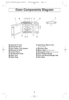
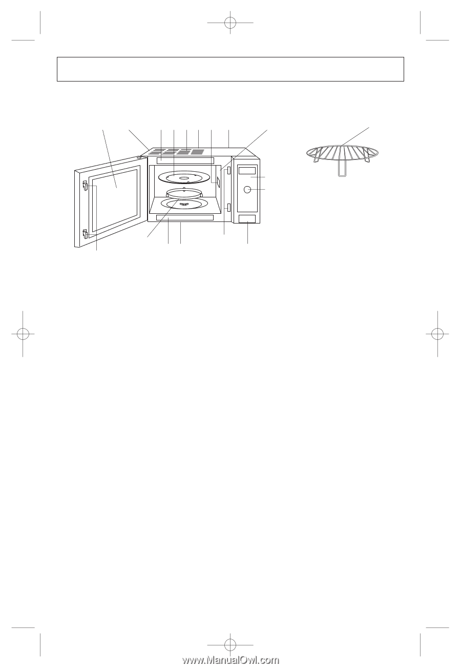
IP1811_38W30CP_Eng_12_080414 2008.4.14 09:52 Page 14 Oven Components Diagram i d jgdfl a b o e n h c c kd m a External Air Vent b Internal Air Vent c Door Safety Lock System d Exhaust Air Vent e Control Panel f Identification Plate g Glass Tray h Roller Ring i Heat/Vapor Barrier Film (do not remove) j Warning Label k Menu Label (do not remove) l Waveguide Cover (do not remove) m Door Release Button n Time and Serving/Weight Dial o Wire Rack 12
-
 1
1 -
2
-
3
-
4
-
5
-
6
-
7
-
8
-
 9
9 -
 10
10 -
 11
11 -
 12
12 -
 13
13 -
 14
14 -
 15
15 -
 16
16 -
 17
17 -
 18
18 -
 19
19 -
20
-
21
-
22
-
23
-
24
-
25
-
26
-
27
-
28
-
29
-
30
-
31
-
32
-
33
-
34
 |
 |
12
Oven Components Diagram
a
External Air Vent
b
Internal Air Vent
c
Door Safety Lock System
d
Exhaust Air Vent
e
Control Panel
f
Identification Plate
g
Glass Tray
h
Roller Ring
i
Heat/Vapor Barrier Film
(do not remove)
j
Warning Label
k
Menu Label
(do not remove)
l
Waveguide Cover
(do not remove)
m
Door Release Button
n
Time and Serving/Weight Dial
o
Wire Rack
o
f
i
d
g
l
a
j
d
b
e
n
d
k
m
h
c
c
IP1811_38W30CP_Eng_12_080414
2008.4.14
09:52
Page 14