Panasonic PT-D12000U Operating Instructions - Page 26
Installation dimensions diagram
 |
View all Panasonic PT-D12000U manuals
Add to My Manuals
Save this manual to your list of manuals |
Page 26 highlights
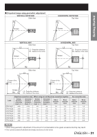
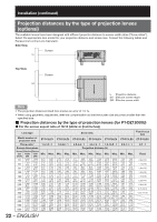
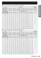
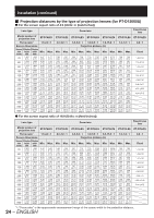
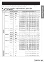
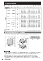
Installation (continued) „ Calculation formulas for projection distance by lens types (for PT-D12000U) Model number of projection lens ET-D75LE1 Throw ratio Aspect ratio 4:3 1.5-2.0 : 1 16:9 4:3 ET-D75LE2 2.0-3.0 : 1 16:9 Zoom lens 4:3 ET-D75LE3 3.0-5.0 : 1 16:9 4:3 ET-D75LE4 5.0-8.0 : 1 16:9 7.9-15.0 : 1 4:3 ET-D75LE8 8.0-15.0 : 1 16:9 4:3 ET-D75LE6 1.0-1.2 : 1 16:9 4:3 ET-D75LE5 0.8 : 1 16:9 Projection distance (L) formula (Units: m) Minimal distance : L = 0.0307 × Screen diagonal (inch) - 0.0760 Maximal distance: L = 0.0410 × Screen diagonal (inch) - 0.1004 Minimal distance : L = 0.0334 × Screen diagonal (inch) - 0.0760 Maximal distance: L = 0.0446 × Screen diagonal (inch) - 0.1004 Minimal distance : L = 0.0412 × Screen diagonal (inch) - 0.0795 Maximal distance: L = 0.0617 × Screen diagonal (inch) - 0.1064 Minimal distance : L = 0.0448 × Screen diagonal (inch) - 0.0795 Maximal distance: L = 0.0672 × Screen diagonal (inch) - 0.1064 Minimal distance : L = 0.0617 × Screen diagonal (inch) - 0.0958 Maximal distance: L = 0.1031 × Screen diagonal (inch) - 0.1216 Minimal distance : L = 0.0672 × Screen diagonal (inch) - 0.0958 Maximal distance: L = 0.1123 × Screen diagonal (inch) - 0.1216 Minimal distance : L = 0.1031 × Screen diagonal (inch) - 0.1158 Maximal distance: L = 0.1639 × Screen diagonal (inch) - 0.1013 Minimal distance : L = 0.1123 × Screen diagonal (inch) - 0.1158 Maximal distance: L = 0.1786 × Screen diagonal (inch) - 0.1013 Minimal distance : L = 0.1640 × Screen diagonal (inch) - 0.3862 Maximal distance: L = 0.3072 × Screen diagonal (inch) - 0.3598 Minimal distance : L = 0.1786 × Screen diagonal (inch) - 0.3862 Maximal distance: L = 0.3346 × Screen diagonal (inch) - 0.3598 Minimal distance : L = 0.0207 × Screen diagonal (inch) - 0.0566 Maximal distance: L = 0.0248 × Screen diagonal (inch) - 0.0736 Minimal distance : L = 0.0225 × Screen diagonal (inch) - 0.0566 Maximal distance: L = 0.0270 × Screen diagonal (inch) - 0.0736 L = 0.0158 × Screen diagonal (inch) - 0.0835 L = 0.0172 × Screen diagonal (inch) - 0.0835 Fixedfocus lens Installation dimensions diagram Figure 1 : Dimensions applying when Figure 2 : Dimensions applying when Figure 3 : Maximum rotation one unit is used two units are used) allowable Exhaust 50 cm (19.7˝) or more Exhaust 50 cm (19.7˝) or more 50 cm (19.7˝) or more +15˃ +15˃ FILTER CLEANING OPEN CLOSE +15˃ +15˃ 30 cm (11.8˝) or more 30 cm (11.8˝) or more 40 cm (15.7˝) or more 50 cm (19.7˝) or more Exhaust 40 cm (15.7˝) or more 10 cm (3.9˝) or more Attention • Leave a clearance of at least 50 cm (19.7˝) so that the ventilation opening on the rear panel will not be blocked. • Set up the projector so that air can flow freely around the rear of the projector. In addition, leave a space of 30 cm (11.8˝) or more at the sides so that the hot air coming out from the air outlet vents does not get drawn in through the air intake vents. • Set up the projector with a space of 40 cm or more at the front so that the air filter can be replaced. • When the projector is to be placed inside a box and used, ensure the structure has a duct or the like to discharge air from the box, leave the clearances shown in Fig. 2, and ensure the temperature during operation remains within the 0 ˃C to 35 ˃C range. 26 - ENGLISH
-
 1
1 -
2
-
3
-
4
-
5
-
6
-
7
-
8
-
9
-
10
-
11
-
12
-
13
-
14
-
15
-
16
-
17
-
18
-
19
-
20
-
 21
21 -
 22
22 -
 23
23 -
 24
24 -
 25
25 -
 26
26 -
 27
27 -
 28
28 -
 29
29 -
 30
30 -
 31
31 -
32
-
33
-
34
-
35
-
36
-
37
-
38
-
39
-
40
-
41
-
42
-
43
-
44
-
45
-
46
-
47
-
48
-
49
-
50
-
51
-
52
-
53
-
54
-
55
-
56
-
57
-
58
-
59
-
60
-
61
-
62
-
63
-
64
-
65
-
66
-
67
-
68
-
69
-
70
-
71
-
72
-
73
-
74
-
75
-
76
-
77
-
78
-
79
-
80
-
81
-
82
-
83
-
84
-
85
-
86
-
87
-
88
-
89
-
90
-
91
-
92
-
93
-
94
-
95
-
96
-
97
-
98
-
99
-
100
-
101
-
102
-
103
-
104
-
105
-
106
-
107
-
108
-
109
-
110
-
111
-
112
-
113
-
114
-
115
-
116
-
117
-
118
-
119
-
120
-
121
-
122
-
123
-
124
-
125
-
126
-
127
-
128
-
129
-
130
-
131
-
132
-
133
-
134
-
135
-
136
-
137
-
138
 |
 |
