Panasonic PT-D4000U Operating Instructions - Page 49
Using the REMOTE 2 terminal
 |
UPC - 791871111529
View all Panasonic PT-D4000U manuals
Add to My Manuals
Save this manual to your list of manuals |
Page 49 highlights
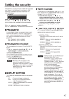
;;;UsingtheREMOTE2terminal Control commands When controlling the projector from a computer, the following commands are available: Using the REMOTE2 IN terminal provided on the side of the main unit, it is possible to operate the projector from a control panel etc. furnished in a distant location where infrared remote control signal cannot be received. Command Function of command PON POF Power "ON" Power "STANDBY" QPW Power query I I S Switch input modes QSL Query for active lamp mode LPM Active lamp mode Remarks To confirm that the power is ON, use a "Power query" command. Parameter 000 = STANDBY 001 = Power "ON" Parameter VID = VIDEO SVD = S-VIDEO RG1 = RGB1 RG2 = RGB2 DVI=DVI-D Parameter 0 = DUAL * "SINGLE" will use 1 = SINGLE the lamp (LAMP 1 2 = LAMP 1 or LAMP 2) with shorter operating 3 = LAMP 2 hours. Parameter 0 = DUAL 1 = SINGLE 2 = Only LAMP 1 is on 3 = Only LAMP 2 is on Note • If you need a detailed command list, please contact your dealer. Cable specifications Projector 1 NC 2 3 4 NC 5 6 NC 7 8 9 NC Computer (DTE specifications) NC 1 2 3 NC 4 5 NC 6 7 8 NC 9 Attention • To connect the computer to the SERIAL terminal, prepare an adequate communication cable that fits to your personal computer. Example of a control panel layout Remote terminal External control Remote terminal /External control STANDBY ON LAMP RGB1 VIDEO RGB2 Projector set up in a meeting room S-VIDEO DVI Control panel located in a different room Pin assignments and control Be sure to short-circuit Pins and when controlling. D-Sub 9-pin (female) external appearance Names of terminals GND POWER RGB1 RGB2 VIDEO S-VIDEO DVI SHUTTER RST / SET Open (H) Short (L) GND OFF ON Other RGB1 Other RGB2 Other VIDEO Other S-VIDEO Other DVI OFF ON Controlled by Controlled by remote control external contact Note • The following buttons on the remote control and the operation area of the projector can no longer be operated when pins and are shorted: POWER button and SHUTTER button. Neither will it be possible to use the RS232C commands or network functions corresponding to these functions. • If you short pin and pin , and also short one of the pins from to and pin , then the following buttons on the projector operating area and the remote control can no longer be operated: POWER, RGB1, RGB2, DVI-D, VIDEO, S-VIDEO and SHUTTER buttons. Neither will it be possible to use the RS232C commands or network functions corresponding to these functions. 49
-
 1
1 -
2
-
3
-
4
-
5
-
6
-
7
-
8
-
9
-
10
-
11
-
12
-
13
-
14
-
15
-
16
-
17
-
18
-
19
-
20
-
21
-
22
-
23
-
24
-
25
-
26
-
27
-
28
-
29
-
30
-
31
-
32
-
33
-
34
-
35
-
36
-
37
-
38
-
39
-
40
-
41
-
42
-
43
-
 44
44 -
 45
45 -
 46
46 -
 47
47 -
 48
48 -
 49
49 -
 50
50 -
 51
51 -
 52
52 -
 53
53 -
 54
54 -
55
-
56
-
57
-
58
-
59
-
60
-
61
-
62
-
63
-
64
-
65
-
66
-
67
-
68
 |
 |
