Panasonic PT-D5600U Dlp Projector- English/french - Page 16
Using A Wired Remote Control, Installation, Projection Schemes, Installation Geometry - lens options
 |
UPC - 791871111352
View all Panasonic PT-D5600U manuals
Add to My Manuals
Save this manual to your list of manuals |
Page 16 highlights
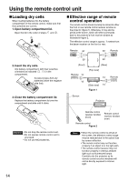
Installation Using the remote control unit Using a wired remote control When multiple main units are connected in the system, connect the units with the M3 stereo mini jack cable available in the market to simultaneously control the multiple main units with a single remote control unit through the REMOTE1 IN/OUT terminal. It is effective to use the wired remote control in the environment in which an obstacle stands in the light path or where devices are susceptible to outside light. Projection schemes Any of the following four projection schemes can be used depending on user's needs or viewing conditions. Use "OPTION2" menu (chosen from the MAIN MENU) to choose the appropriate projection scheme (see page 35). Projection Scheme 2 Table standing Ceiling mount R/PR G/Y B/PB S ;VIDEO IN S-VIDEO IN REMOTE 1 Projection Scheme 1 Rear projection Front projection IN OUT RGB 1 IN REMOTE 2 Connect to the secondary projector M3 stereo mini jack cable (available in the ;;;market) 421-541 (16 37/64-21 19/64) SH SW 157 (6 3/16) 314 (12 23/64) (Default position) Installation geometry After the projector is roughly positioned, picture size and vertical picture positioning can be finely adjusted with the powered zoom lens and lens tilt mechanism. Side view With optional ceiling mount bracket (ET-PKD55) H L 180 261 (7 3/32) (10 9/32) L H Screen L : Projection distance SH : Image height SW : Image width H : Distance from center of lens to bottom edge Attention • Use two-core shielded cable of of projected image. length smaller than 15 m (49' 2"). If Top view the cable length exceeds 15 m (49' 2"), or if the shielding of the cable is inadequate, the operation may be unsatisfactory. L 16 87.5 (3 29/64) Screen 175 (6 57/64) Attention • Do not place or use one projector on top of another projection unit. • Leave a clearance of at least 50 cm so that the ventilation opening on the rear panel will not be blocked.
-
 1
1 -
2
-
3
-
4
-
5
-
6
-
7
-
8
-
9
-
10
-
 11
11 -
 12
12 -
 13
13 -
 14
14 -
 15
15 -
 16
16 -
 17
17 -
 18
18 -
 19
19 -
 20
20 -
 21
21 -
22
-
23
-
24
-
25
-
26
-
27
-
28
-
29
-
30
-
31
-
32
-
33
-
34
-
35
-
36
-
37
-
38
-
39
-
40
-
41
-
42
-
43
-
44
-
45
-
46
-
47
-
48
-
49
-
50
-
51
-
52
-
53
-
54
-
55
-
56
-
57
-
58
-
59
-
60
-
61
-
62
-
63
-
64
-
65
-
66
-
67
-
68
 |
 |
