Panasonic SC-PT665 Dvd Home Theater Sound System - Page 8
Audio and video connections Continued, Speaker connections, Radio antenna connections
 |
UPC - 037988984039
View all Panasonic SC-PT665 manuals
Add to My Manuals
Save this manual to your list of manuals |
Page 8 highlights
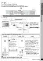
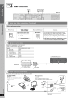
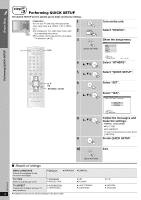
Simple Setup Cable connections 2 step Cable connections 2 SUBWOOFER CENTER FRONT SURROUND 31 AM ANT EXT LOOP FM ANT (75 ) LOOP ANT GND OPTICAL IN Main unit 1 Audio and video connections (Continued) Other audio connection TV terminal OPTICAL OUT Cable required (not included) Optical digital audio cable ≥ Do not bend sharply when connecting. Main unit terminal Features [\\\\\\OPTICAL\IN\\\\\\] OPTICAL IN This unit can decode the surround signals received through cable TV box, digital broadcasting or satellite broadcasts. Refer to your equipment's operating instructions for details. Only Dolby Digital and PCM can be played with this connection. ≥ After making this connection, make settings to suit the type of audio from your digital equipment (➜ 28). 2 Speaker connections Connecting the speakers to the main unit: Connect to terminals of the same color. Speaker 1 FRONT (L) 2 FRONT (R) 3 SURROUND (L) 4 SURROUND (R) 5 CENTER 6 SUBWOOFER Terminal/connector color White Red Blue Gray Green Purple e.g. Surround speaker Main unit 6 SUBWOOFER 521 R L CENTER FRONT 43 R L SURROUND Insert fully. 3 Radio antenna connections ≥ Keep loose antenna cables away from other wires and cables. [FM\indoor\antenna] (included) Affix this end of the antenna where reception is best. [AM\loop\antenna] (included) Stand the antenna up on its base. Place the antenna where reception is best. Adhesive tape Click! Black Red White AM ANT EXT LOOP FM ANT (75 ) 2 1 3 LOOP ANT GND Push! RQTX0275 Main unit 8
-
 1
1 -
2
-
 3
3 -
 4
4 -
 5
5 -
 6
6 -
 7
7 -
 8
8 -
 9
9 -
 10
10 -
 11
11 -
 12
12 -
 13
13 -
14
-
15
-
16
-
17
-
18
-
19
-
20
-
21
-
22
-
23
-
24
-
25
-
26
-
27
-
28
-
29
-
30
-
31
-
32
-
33
-
34
-
35
-
36
-
37
-
38
-
39
-
40
-
41
-
42
-
43
-
44
-
45
-
46
-
47
-
48
-
49
-
50
-
51
-
52
-
53
-
54
-
55
-
56
-
57
-
58
-
59
-
60
-
61
-
62
-
63
-
64
-
65
-
66
-
67
-
68
-
69
-
70
-
71
-
72
 |
 |
