Panasonic SDC615 AJSDC615 User Guide - Page 13
VIDEO OUT CHARACTER switch - dvcpro aj
 |
UPC - 791871302699
View all Panasonic SDC615 manuals
Add to My Manuals
Save this manual to your list of manuals |
Page 13 highlights
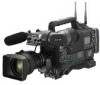
Chapter 2 Parts and their functions = OUTPUT SEL (output signal selection) switch This is used to select the signals output from the VIDEO OUT connector and MON OUT connector. VTR : In the recording or other EE mode, the camera images are output from the connectors; in the playback or other VV mode, it is the VTR's playback signals which are output. CAM : The camera images are output at all times. OFF : The video output is stopped and the power reduction mode is established. Furthermore, the audio output signals are synchronized with the video signals as well. For details on the video output, refer to "4-8-2 Selecting the video output signals." O During recording, the output signals are not switched even when the position of this switch is changed. They are switched when the recording operation is stopped. O When the signals input to the GENLOCK IN connector or DVCPRO connector are selected as the signals to be recorded, the switch setting will be the same as at the VTR position even if the switch is set at the CAM position. > VIDEO OUT CHARACTER switch This is used to control the superimposing of the characters onto the images which are output from the VIDEO OUT connector. ON : The characters are superimposed onto the images. OFF : The characters are not superimposed onto the images. For details on the character types, refer to "4-8-2 Selecting the video output signals." ? VIDEO OUT (video signal output) connector This is the video signal output connector. The video signals linked to the setting of the OUTPUT SEL switch are output from here. @ ECU REMOTE (remote control) connector The AJ-EC3P extension control unit (optional accessory) is connected here. A MON OUT (monitor output) connector This is the connector for outputting the video signal which is used for monitoring. The video signals linked to the setting of the OUTPUT SEL switch are output from here. Whether characters are to be superimposed onto the images output from the VIDEO OUT connector can be selected separately using the internal menu. For details, refer to "4-8-2 Selecting the video output signals." B GENLOCK IN connector The reference signal is input to this connector when genlock is to be established with the camera unit or when 2 the time code is to be externally locked. This signal can also be used as the return signal. The connector serves as a video input connector for receiving the video signals from an external unit when the screen is opened from the SYSTEM SETTING page by performing menu operations and VIDEO is selected as the REC SIGNAL menu item setting. A standard VBS signal (a composite signal including a burst signal) should be supplied as the input reference signal. C DVCPRO connector (6-pin) This is the input/output connector for signals which comply with the IEEE 1394 standard. It can be connected with an external unit using an IEEE 1394 cable. O Power is not supplied from the unit. O Before proceeding to connect or disconnect the DV cable (IEEE1394), be absolutely sure to turn off the power of the units that are to be connected or disconnected using this cable. O Before proceeding to connect the unit which uses a 6-pin type of DV connector, carefully check the shape of the connectors on the DV cable 6-pin type and unit. Connecting a connector upside down may 4-pin type damage the parts inside the camera-recorder and cause malfunctioning. Always connect the DV cable to the unit with the 6-pin type DV connector first. O When recording signals from an external unit, first check that video signals are supplied. O While signals from an external unit are being recorded, do not operate the external unit or disconnect any of its cables. This will stop the output, which may result in the signals not being recognized when recording is resumed. O You can connect a digital video unit equipped with a DV connector and digitally transfer video and audio signals as well as time codes and other information. O When a DV cable has been connected to the DV connector, do not apply any strong external force as this may damage the connector. D EJECT button This is pressed to insert or eject the cassette. E STOP button This is pressed to stop the tape travel. 13
-
 1
1 -
2
-
3
-
4
-
5
-
6
-
7
-
 8
8 -
 9
9 -
 10
10 -
 11
11 -
 12
12 -
 13
13 -
 14
14 -
 15
15 -
 16
16 -
 17
17 -
 18
18 -
19
-
20
-
21
-
22
-
23
-
24
-
25
-
26
-
27
-
28
-
29
-
30
-
31
-
32
-
33
-
34
-
35
-
36
-
37
-
38
-
39
-
40
-
41
-
42
-
43
-
44
-
45
-
46
-
47
-
48
-
49
-
50
-
51
-
52
-
53
-
54
-
55
-
56
-
57
-
58
-
59
-
60
-
61
-
62
-
63
-
64
-
65
-
66
-
67
-
68
-
69
-
70
-
71
-
72
-
73
-
74
-
75
-
76
-
77
-
78
-
79
-
80
-
81
-
82
-
83
-
84
-
85
-
86
-
87
-
88
-
89
-
90
-
91
-
92
-
93
-
94
-
95
-
96
-
97
-
98
-
99
-
100
-
101
-
102
-
103
-
104
-
105
-
106
-
107
-
108
 |
 |
