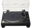
Panasonic SL-1200MK2PK Service Manual - Page 2
MK2/1210MK2
 |
View all Panasonic SL-1200MK2PK manuals
Add to My Manuals
Save this manual to your list of manuals |
Page 2 highlights
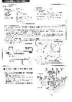
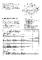
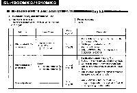
-1200MK2/1210MK2 ■ Tonearm section Type: Effective length: Arm height adjustment range: Overhang: Effective mass: Offset angle: Friction: Tracking error angle: Universal 230 mm (9-1/16") 0 - 6 mm 15 mm (19/32") 12 g (without cartridge) 22° Less than 7 mg (lateral, vertical) Within 2°32' (at the outer groove of 30 cm (12") record Within 0° 32' (at the inner groove of 30 cm (12") record Stylus pressure adjustment range: 0 - 2.5 g Applicable cartridge weight range: 6 - 10 g 13.5 - 17.5 g (including headshell) (with auxiliary weight): 9.5 - 13 g 17 - 20.5 g (including headhsell) (with shell weight): 3.5 - 6.5 g 11 - 14g (including headshell) Headshell weight: 7.5 g C Notes * To improve the performance of SL-1200MK2/1210MK2, the bottom structure and circuit are changed in the course of production. * After the change, SL1200MK2-A/1210MK2-A is indicated in the name plate as the model of the set. It is discriminated from before-change set by -A. Also, check that the present change is of the sets after the change mark E shown in the sirial No. sheet attached to the bottom and carton box. * This supplement service manual contains the bottom plate disassembly procedure, change part No., circuit diagram, P.C.B. and block diagrams. The other contents are the same as for the service manual of SL-1200MK2/1210MK2 already issued. * Sets with cartridge (EPC-207C) are included in those for same areas. * Since the power transformer fitting method is different for sets with serial number sheet change mark ❑E , refer to the development plan on page 8. 0 Ct Name plate MODEL SL-1200MK2-A Serial No. sheet O 011111111111MEMEI SER.No. -Change mark Serial No. sheet ■ DISASSEMBLY INSTRUCTIONS 0 0 • How to remove the bottom cover and bottom base. Insulator x 4 1. Remove the turntable mat and turntable. 2. Turn over the body on a soft cloth thaking care not to 0 damage the dust cover. x4 3. Remove the insulators and the 21 setscrews (Fig. 1 : 0,0,0) of the bottom cover. 4. Remove the 6 setscrews (Fig. 2 : 0) of the bottom base. Bottom cover Fig. 1
-
 1
1 -
 2
2 -
 3
3 -
 4
4 -
 5
5 -
 6
6 -
 7
7 -
 8
8 -
9
-
10
-
11
-
12
-
13
-
14
-
15
-
16
 |
 |
