Panasonic SL-1200MK2PK Service Manual - Page 8
Assembling, Procedure, Adjustment, Canceller, Spring, Position
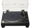 |
View all Panasonic SL-1200MK2PK manuals
Add to My Manuals
Save this manual to your list of manuals |
Page 8 highlights
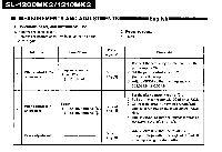
SL-1200MK ■ ARM BASE ASSEMBLING PROCEDURE 1. Attach the control ring to the arm base seat. (The control ring should be roated counterclockwise.) 2. Completely tighten the control ring, and then loosen it 1.5-2.5 turns to set the scale to "3". (See Fig. 11) 5. Rotate the control ring and make sure that the arm base shifts within the range of 0-6mm. (See Figs, 14 and 15) If it does not shift within the specified range, the arm base position is deflected. In that case, disassemble the parts and check as specified in step 3. Operating r Arm rase N.Y Fig. 11 3. Hold the arm base and set the red line mark on the arm base to the scale near "2", then turn the arm base clockwise. (See Fig, 12) Note: Take care not to allow deflection of the predetermined positions of the control ring and arm base seat. .91 Iii Fig. 14 Fig. 12 4. Adjust the arm base so that the red line mark on the arm base is set to the scale "3" of the control ring. Next, secure the positioning base plate with two setscrews. (See Fig. 13) Fig, 15 ■ ADJUSTMENT OF CANCELLER SPRING POSITION If the arm body or PU base plate is replaced, be sure to set the canceller knob to "0.5" and make sure that the canceller spring is in contact with the arm shaft. (See Fig. 16) If the canceller spring is deflected, adjust it as follows: 1, Clamp the arm on the rest. 2. Set the canceller knob to "0.5". 3. Remove the PU base plate, adjust gear 0 so that the canceller spring is in the position of Fig. 16. 4. Mount the PU base plate onto the arm base and check the spring position, ( Fig. 13 Cane er,Spr ngr, Fig, 16 r5-1
-
 1
1 -
2
-
 3
3 -
 4
4 -
 5
5 -
 6
6 -
 7
7 -
 8
8 -
 9
9 -
 10
10 -
 11
11 -
 12
12 -
 13
13 -
14
-
15
-
16
 |
 |
