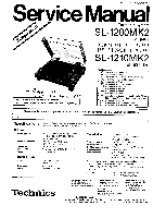
Panasonic SL-1200MK2PK Service Manual - Page 6
Disassembly, Procedure
 |
View all Panasonic SL-1200MK2PK manuals
Add to My Manuals
Save this manual to your list of manuals |
Page 6 highlights
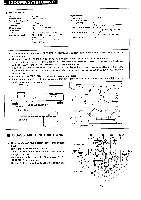
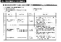
bi • DISASSEMBLY PROCEDURE How to remove panel cover 1. Remove head shell and turntable. 2. Secure arm with arm clamp. 3. Remove 5 screws 0 of the panel cover as shown in Fig. 1. How to remove stater frame coil and F.G detector coil 4. Remove 3 connectors 0 and 2 read wires ® from power transformer as shown in Fig. 2. 5. Remove 3 screws 0 of the drive circuit board and 3 screws Q of the stater frame cover as shown in Fig. 2. 6. Disconnect 18 soldered parts 0 of the stater coil and 4 soldered parts O of the F.G detector coil as show in Fig. 3. 7. Remove 3 screws Q of the stater frame ass'y as shown in Fig. 3. How to remove bottom base ass'y 8. Remove 4 audio insulators. (Counterclockwise rotation) 9. Remove 17 screws and spacer Q as show in Fig. 4. 10. Remove 11 screws 0 as shown in Fig. 4. How to remove stylus-illuminator lamp 11. Remove 2 screws 0 of the stylus-illuminator lamp ass'y as shown in Fig. 5. 12. Remove 1 screw 0 as shown in Fig. 6. How to remove neon-illuminator L.E.D. 13. Remove 4 screws 0 as shown in Fig. 5. 14. Remove 1 circlip 0 and switch cam V. as shown in Fig. 5. 15. Remove strobe-illuminator case. How to remove tone arm 16. Remove 4 screws 0 of the arm base cover as shown in Fig. 5. 17. Remove 2 screws () of the phono cord damper as shown in Fig. 5. 18. Remove phono cord damper as shown in Fig. 7. 19. Remove 2 screws Q of the phono cord p.c.b. as shown in Fig. 8. 20. Remove 2 screws 0 as shown in Fig. 8. 21. Remove 2 screws 0 of the silicon oil dumper as shown in Fig. 8. 22. Remove 3 screws as shown in Fig. 8. 23, Remove 2 screws 0 of the tone arm as shown in Fig. 9. 9 Fig, 1 Fig. 2 Dove PC.13 r. • kw? Fig. 3 I3i
-
 1
1 -
 2
2 -
 3
3 -
 4
4 -
 5
5 -
 6
6 -
 7
7 -
 8
8 -
 9
9 -
 10
10 -
 11
11 -
 12
12 -
13
-
14
-
15
-
16
 |
 |
