Panasonic TC-54PS14 Service Manual - Page 18
Disassembly and Assembly Instructions - p board
 |
View all Panasonic TC-54PS14 manuals
Add to My Manuals
Save this manual to your list of manuals |
Page 18 highlights
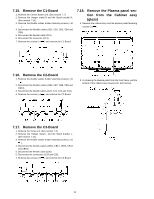
7 Disassembly and Assembly Instructions 7.1. Remove the Rear cover 1. See Service Hint (Section 3) 7.2. Remove the P-Board Caution: To remove P.C.B. wait 1 minute after power was off for discharge from electrolysis capacitors. 1. Unlock the cable clampers to free the cable 2. Disconnect the connectors (P51-P52, P53-P54, P55-P56 and P57-P58). 3. Disconnect the connectors (P2, P6, P7, P9, P11, P25 and P35). 4. Remove the screws (×9 ) and remove the P(P-1)-Board. 5. Remove the screws (×6 ) and remove the P(P-2)-Board. 3. Remove the Adjustment cover. 4. Remove the screws (×4 , ×3 , ×1 ). 5. Remove the Rear terminal cover. 7.4. Remove the Tuner unit 1. Unlock the cable clampers to free the cable. 2. Disconnect the connectors (A1, A6 A11, A12, A25 and A30). 3. Disconnect the flexible cables (A31, A32 and A33). 4. Remove the screws (×2 ) and remove the Tuner unit. 7.3. Remove the Side terminal cover and Rear terminal cover 1. Remove the claw (×1 ). 2. Remove the Side terminal cover. 18
-
 1
1 -
2
-
3
-
4
-
5
-
6
-
7
-
8
-
9
-
10
-
11
-
12
-
 13
13 -
 14
14 -
 15
15 -
 16
16 -
 17
17 -
 18
18 -
 19
19 -
 20
20 -
 21
21 -
 22
22 -
 23
23 -
24
-
25
-
26
-
27
-
28
-
29
-
30
-
31
-
32
-
33
-
34
-
35
-
36
-
37
-
38
-
39
-
40
-
41
-
42
-
43
-
44
-
45
-
46
-
47
-
48
-
49
-
50
-
51
-
52
-
53
-
54
-
55
-
56
-
57
-
58
-
59
-
60
-
61
-
62
-
63
-
64
-
65
-
66
-
67
-
68
-
69
-
70
-
71
-
72
-
73
-
74
-
75
-
76
-
77
-
78
-
79
-
80
-
81
-
82
-
83
-
84
-
85
-
86
-
87
-
88
-
89
-
90
-
91
-
92
-
93
-
94
-
95
-
96
-
97
-
98
-
99
-
100
-
101
-
102
-
103
-
104
-
105
-
106
-
107
-
108
-
109
-
110
-
111
-
112
-
113
-
114
-
115
-
116
-
117
-
118
-
119
-
120
-
121
 |
 |
