Panasonic TC-54PS14 Service Manual - Page 22
Remove the C1-Board, Remove the C2-Board, Remove the C3-Board, Remove the Plasma panel sec, tion - stand
 |
View all Panasonic TC-54PS14 manuals
Add to My Manuals
Save this manual to your list of manuals |
Page 22 highlights
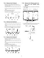
7.15. Remove the C1-Board 1. Remove the Control button unit. (See section 7.7.) 2. Remove the Hanger metal R and the Stand bracket R. (See section 7.14.) 3. Remove the flexible cables holder fastening screws (×10 ). 4. Disconnect the flexible cables (CB1, CB2, CB3, CB4 and CB5). 5. Disconnect the flexible cable (C10). 6. Disconnect the connector (C14). 7. Remove the screws (×4 ) and remove the C1-Board. 7.18. Remove the Plasma panel section from the Cabinet assy (glass) 1. Remove the cabinet assy and the plasma panel fastening screws (×2 ). 7.16. Remove the C2-Board 1. Remove the flexible cables holder fastening screws (×10 ). 2. Disconnect the flexible cables (CB6, CB7, CB8, CB9 and CB10). 3. Disconnect the flexible cables (C20, C21, C22 and C26). 4. Remove the screws (×4 ) and remove the C2-Board. 2. For leaving the plasma panel from the front frame, pull the bottom of the cabinet assy forward, lift, and remove. 7.17. Remove the C3-Board 1. Remove the Tuner unit. (See section 7.4.) 2. Remove the Hanger metal L and the Stand bracket L. (See section 7.14.) 3. Remove the flexible cables holder fastening screws (×10 ). 4. Disconnect the flexible cables (CB11, CB12, CB13, CB14 and CB15). 5. Disconnect the flexible cable (C36). 6. Disconnect the connectors (C33 and C35). 7. Remove the screws (×5 ) and remove the C3-Board. 22
-
 1
1 -
2
-
3
-
4
-
5
-
6
-
7
-
8
-
9
-
10
-
11
-
12
-
13
-
14
-
15
-
16
-
 17
17 -
 18
18 -
 19
19 -
 20
20 -
 21
21 -
 22
22 -
 23
23 -
 24
24 -
 25
25 -
 26
26 -
 27
27 -
28
-
29
-
30
-
31
-
32
-
33
-
34
-
35
-
36
-
37
-
38
-
39
-
40
-
41
-
42
-
43
-
44
-
45
-
46
-
47
-
48
-
49
-
50
-
51
-
52
-
53
-
54
-
55
-
56
-
57
-
58
-
59
-
60
-
61
-
62
-
63
-
64
-
65
-
66
-
67
-
68
-
69
-
70
-
71
-
72
-
73
-
74
-
75
-
76
-
77
-
78
-
79
-
80
-
81
-
82
-
83
-
84
-
85
-
86
-
87
-
88
-
89
-
90
-
91
-
92
-
93
-
94
-
95
-
96
-
97
-
98
-
99
-
100
-
101
-
102
-
103
-
104
-
105
-
106
-
107
-
108
-
109
-
110
-
111
-
112
-
113
-
114
-
115
-
116
-
117
-
118
-
119
-
120
-
121
 |
 |
