Panasonic TC-54PS14 Service Manual - Page 28
Adjustment
 |
View all Panasonic TC-54PS14 manuals
Add to My Manuals
Save this manual to your list of manuals |
Page 28 highlights
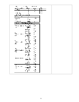
8.2. Adjustment 8.2.1. White balance adjustment Name of measuring instrument Connection • W/B pattern Component input • Color analyzer or HDMI input (Minolta CA-100 or equivalent) or ATSC 1080i signal Panel surface Procedure • Make sure the front panel to be used on the final set is fitted. • Make sure a color signal is not being shown before adjustment. • Put the color analyzer where there is little color variation. 1. Set the Picture menu to [vivid] and output the W/B pattern. Remarks Remarks 2. Check that the color temperature is [Cool]. 3. Set to serviceman mode, WB-ADJ. 4. Set [R-CUT] [G-CUT] [B-CUT] the values written in table 1. 5. Attach the sensor of color analyzer to the center of highlight window. 6. Fix G drive at C0h and adjust [B-DRV] and [R-DRV] so x, y value of color analyzer become the [Color temperature High] in table 2. 7. Increase RGB together so the maximum drive value in RGB becomes FC. That is, set [ALL DRIVE] to FC. Execute adjustment again. When that, the maximum value of R/G/B DRV should be FC, and either R/G/B DRV should be FC. 8. Set color temperature to [Normal]. 9. Set [R-CUT] [G-CUT] [B-CUT] the values written in table 1. 10. Attach the sensor of color analyzer to the center of highlight window. 11. Fix G drive at C0h and adjust [B-DRV] and [R-DRV] so x, y value of color analyzer become the [Color temperature Mid] in table 2. 12. Increase RGB together so the maximum drive value in RGB becomes FC. That is, set [ALL DRIVE] to FC. Execute adjustment again. When that, the maximum value of R/G/B DRV should be FC, and either R/G/B DRV should be FC. 13. Set color temperature to [Warm]. 14. Set [R-CUT] [G-CUT] [B-CUT] the values written in table 1. 15. Attach the sensor of color analyzer to the center of highlight window. 16. Fix G drive at C0h and adjust [B-DRV] and [R-DRV] so x, y value of color analyzer become the [Color temperature Low] in table 2. 17. Increase RGB together so the maximum drive value in RGB becomes FC. That is, set [ALL DRIVE] to FC. Execute adjustment again. When that, the maximum value of R/G/B DRV should be FC, and either R/G/B DRV should be FC. 18. Set color temperature to [Cool]. 28
-
 1
1 -
2
-
3
-
4
-
5
-
6
-
7
-
8
-
9
-
10
-
11
-
12
-
13
-
14
-
15
-
16
-
17
-
18
-
19
-
20
-
21
-
22
-
 23
23 -
 24
24 -
 25
25 -
 26
26 -
 27
27 -
 28
28 -
 29
29 -
 30
30 -
 31
31 -
 32
32 -
 33
33 -
34
-
35
-
36
-
37
-
38
-
39
-
40
-
41
-
42
-
43
-
44
-
45
-
46
-
47
-
48
-
49
-
50
-
51
-
52
-
53
-
54
-
55
-
56
-
57
-
58
-
59
-
60
-
61
-
62
-
63
-
64
-
65
-
66
-
67
-
68
-
69
-
70
-
71
-
72
-
73
-
74
-
75
-
76
-
77
-
78
-
79
-
80
-
81
-
82
-
83
-
84
-
85
-
86
-
87
-
88
-
89
-
90
-
91
-
92
-
93
-
94
-
95
-
96
-
97
-
98
-
99
-
100
-
101
-
102
-
103
-
104
-
105
-
106
-
107
-
108
-
109
-
110
-
111
-
112
-
113
-
114
-
115
-
116
-
117
-
118
-
119
-
120
-
121
 |
 |
