Panasonic TH32LRT12U TH32LRT12U User Guide - Page 12
PC Input Terminals connection
 |
UPC - 037988108848
View all Panasonic TH32LRT12U manuals
Add to My Manuals
Save this manual to your list of manuals |
Page 12 highlights
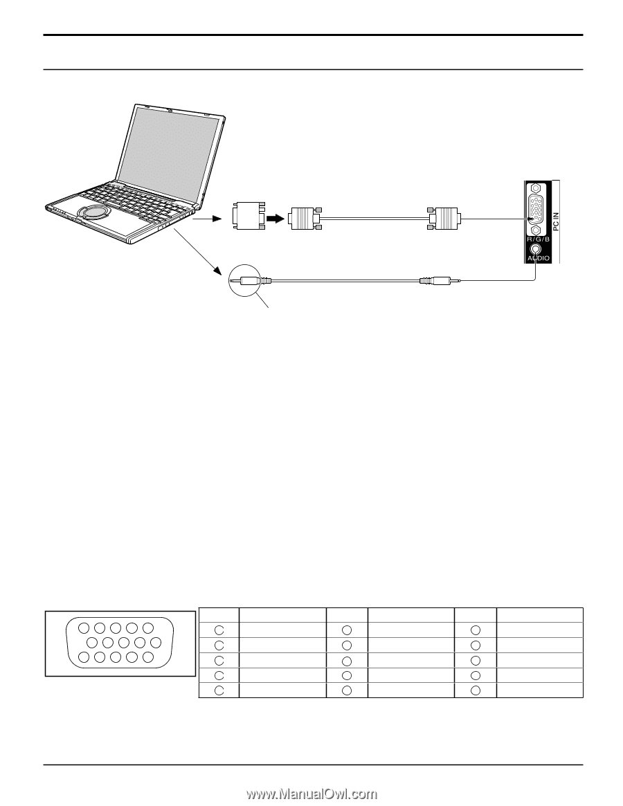
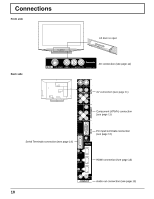
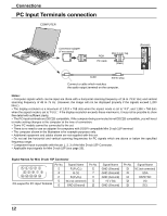
Connections PC Input Terminals connection COMPUTER Conversion adapter (if necessary) RGB PC cable Mini D-sub 15p (Male) (Female) Audio Stereo plug Connect a cable which matches the audio output terminal on the computer. Notes: • Computer signals which can be input are those with a horizontal scanning frequency of 15 to 79.97 kHz and vertical scanning frequency of 48 to 75 Hz. (However, the image will not be displayed properly if the signals exceed 1,200 lines.) • The display resolution is a maximum of 1,024 × 768 dots when the aspect mode is set to "4:3", and 1,366 × 768 dots when the aspect mode is set to "FULL". If the display resolution exceeds these maximums, it may not be possible to show fine detail with sufficient clarity. • The PC input terminals are DDC2B-compatible. If the computer being connected is not DDC2B-compatible, you will need to make setting changes to the computer at the time of connection. • Some PC models cannot be connected to the set. • There is no need to use an adapter for computers with DOS/V compatible Mini D-sub 15P terminal. • The computer shown in the illustration is for example purposes only. • Additional equipment and cables shown are not supplied with this set. • Do not set the horizontal and vertical scanning frequencies for PC signals which are above or below the specified frequency range. • Component Input is possible with the pin 1, 2, 3 of the Mini D-sub 15P Connector. • Applicable input signals for Mini D-sub 15P (see page 29). Signal Names for Mini D-sub 15P Connector 54 321 10 9 8 7 6 15 14 13 12 11 Pin Layout for PC Input Terminal Pin No. 1 2 3 4 5 Signal Name R (PR/CR) G (Y) B (PB/CB) NC (not connected) GND (Ground) Pin No. 6 7 8 9 10 Signal Name GND (Ground) GND (Ground) GND (Ground) +5 V DC GND (Ground) Pin No. 11 12 13 14 15 Signal Name NC (not connected) SDA HD/SYNC VD SCL 12
-
 1
1 -
2
-
3
-
4
-
5
-
6
-
 7
7 -
 8
8 -
 9
9 -
 10
10 -
 11
11 -
 12
12 -
 13
13 -
 14
14 -
 15
15 -
 16
16 -
 17
17 -
18
-
19
-
20
-
21
-
22
-
23
-
24
-
25
-
26
-
27
-
28
-
29
-
30
-
31
-
32
-
33
-
34
 |
 |