Panasonic TH50PHD6 42" Plasma Tv - Page 9
Connections
 |
View all Panasonic TH50PHD6 manuals
Add to My Manuals
Save this manual to your list of manuals |
Page 9 highlights
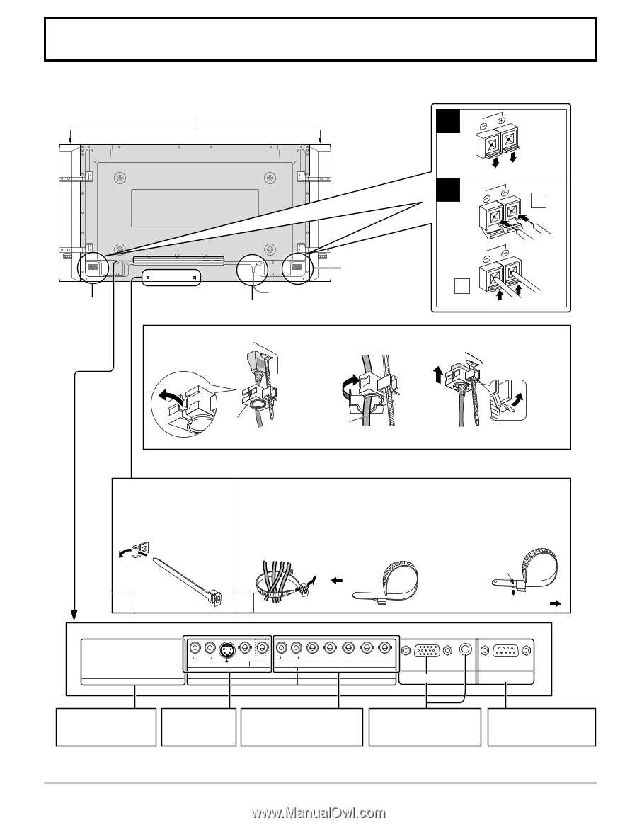
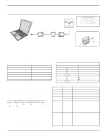
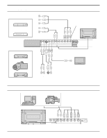
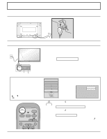
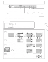
Connections When connecting the speakers, be sure to use only the optional accessory speakers. Refer to the speaker's Installation Manual for details on speaker installation. (Example : TH-42PWD6) Speakers (Optional accessories) 1 2 1 SPEAKERS Terminals (R) SPEAKERS Terminals (L) 2 AC cord connection (see page 13) - AC cord fixing 1. Open the clamper. 2. Insert the AC cord and close the clamper securely. 3. Slide up the clamper and fix the AC cord plug securely. When loosen the clamper: Clamper AC cord Note: The power plug in the illustration may not be the type fitted to your set. - Cable fixing bands Secure any excess cables with bands as required. Pass the attached cable fixing band through the clip as shown in the figure. To secure cables connected to Terminals, wrap the cable fixing band around them then pass the pointed end through the locking block, as shown in the figure. While ensuring there is sufficient slack in cables to minimize stress (especially in the power cord), firmly bind all cables with the supplied fixing band. To tighten: To loosen: Push the catch Pull 1 2 Pull SLOT1 R AUDIO L VIDEO IN VIDEO OUT R AUDIO L VD HD PR/CR/R PB/CB/B Y/G IN S VIDEO IN AV COMPONENT/RGB IN SLOT2 SLOT3 AUDIO PC IN SERIAL Optional Terminal Board Insert Slot (covered) AV Terminals (see page12) COMPONENT/RGB IN and Audio IN Terminals (see page12) From EXTERNAL monitor terminal on Computer (see page 10) Note: At factory shipment, Terminal boards are installed in SLOT 2 and SLOT 3. TH-37PWD6 has 2 SLOTs only. From SERIAL Terminal on Computer (see page 11) 9
-
 1
1 -
2
-
3
-
 4
4 -
 5
5 -
 6
6 -
 7
7 -
 8
8 -
 9
9 -
 10
10 -
 11
11 -
 12
12 -
 13
13 -
 14
14 -
15
-
16
-
17
-
18
-
19
-
20
-
21
-
22
-
23
-
24
-
25
-
26
-
27
-
28
-
29
-
30
-
31
-
32
-
33
-
34
-
35
-
36
-
37
-
38
-
39
-
40
 |
 |