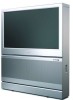
Philips 51PP9303H User manual - Page 9
Connecting
 |
View all Philips 51PP9303H manuals
Add to My Manuals
Save this manual to your list of manuals |
Page 9 highlights
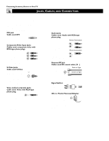
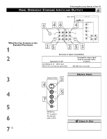
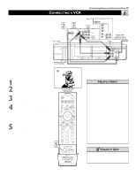
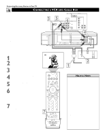
CONNECTING A VCR Connecting Accessory Devices to Your TV T he TV's audio/video (AV) input jacks provide for direct picture and sound connections between the TV and accessory devices such as VCRs, DVD players, and others that have AV output jacks. This example, which uses the INPUT-AV 1 jacks, shows you one way you can connect a VCR to your TV. Refer to the directions-for-use manual for your VCR for further information on connections. To make the connections shown in this example, you will need: • one coaxial cable (75Ω) • one cable for a video connection (standard RCA-type phono plug) • two cables for audio connections (standard RCA-type phono plugs) (only one cable is needed for a nonstereo VCR). NOTE: The cables are not supplied with your TV. You should be able to buy them at most stores that sell electronics. Or you can call our Customer Care Center at 1-800-531-0039 2 Rear of VCR* * (Example: Philips VCR model VR674CAT) AV1 3 ANTENNA IN 75Ω INPUT-AV 1 VIDEO S-VIDEO L L AUDIO R Rear of TV DVI 4OUTPUT INPUT-AV 2 Y VIDEO S-VIDEO Pb L L Pr AUDIO R HD INPUT-AV 5 HD INPUT-AV 4 G/Y R/Pr B/Pb V L SYNC AUDIO H R L Coaxial Cable AUDIO Lead-in from R Cable TV Company or VHF/UHF Antenna 1 AUDIO L IN R VIDEO ANT IN OUT OUT IN CH3 CH4 1 Connect a cable TV or antenna signal to the ANT IN jack on the back of the VCR. 2 Connect from the OUT jack on the back of the VCR to the ANTENNA IN 75Ω jack on the back of the TV. 3 Connect the VIDEO OUT jack on the back of the VCR to the INPUT-AV 2 VIDEO jack on the back of the TV. 4 Connect the audio output R(ight) and L(eft) jacks on the back of the VCR to the INPUT-AV 2 AUDIO jacks on the back of the TV. NOTE: If the VCR is a mono (nonstereo) unit, connect only the left audio cable, which usually has a white-coded plug. 5 Press the AV button on the remote control as many times as necessary to select the AV2 source for viewing of materials from the VCR. POWER TV SWAP VCR PIP CH ACC ACTIVE CONTROL FREEZE DN UP SOUND PICTURE STATUS/ EXIT MENU/ SELECT MUTE VOL CH 5 123 456 789 TV/VCR A/CH 0 SURF SURF PIP ON/OFF REC • FORMAT SLEEP SAP AV DOLBY V PROG.LIST ITR/ RECORD HOME VIDEO HOME PERSONAL MOVIES POSITION PIP HELPFUL HINTS • Stereo sound will pass from the ANT OUT jack on the VCR to the ANTENNA IN 75Ω jack on the TV only when the VCR is in TV mode. This is the mode that allows the TV to use its channel selector. • To simplify making connections, audio and video cables often have color-coded plugs. The jacks on your TV are likewise color coded to match the plugs. The coding is as follows: -Yellow for video (composite) -Red for the right audio channel -White for the left audio channel NOTE: If your VCR is mono (nonstereo), you will connect only one audio cable. You must ensure that the TV is set to MONO for the signal source to which you've connected the VCR (INPUT-AV 2, INPUT-AV 1, or the side panel inputs [AV3]). Otherwise, you will receive sound from only one of the TV's speakers. See page 36. c CHECK IT OUT You can display the AV1, AV2, or AV3 signal sources in the PIP window. See page 7 of the Quick Use and Setup Guide for information on using the Picture-in-Picture (PIP) feature. 9
-
 1
1 -
2
-
3
-
 4
4 -
 5
5 -
 6
6 -
 7
7 -
 8
8 -
 9
9 -
 10
10 -
 11
11 -
 12
12 -
 13
13 -
 14
14 -
15
-
16
-
17
-
18
-
19
-
20
-
21
-
22
-
23
-
24
-
25
-
26
-
27
-
28
-
29
-
30
-
31
-
32
-
33
-
34
-
35
-
36
-
37
-
38
-
39
-
40
-
41
-
42
-
43
-
44
-
45
-
46
-
47
-
48
-
49
-
50
-
51
-
52
-
53
-
54
-
55
-
56
-
57
-
58
-
59
-
60
-
61
-
62
-
63
-
64
-
65
-
66
-
67
-
68
-
69
-
70
-
71
-
72
 |
 |
