Pioneer AVIC-X910BT Installation Manual - Page 6
Before installing this product, To prevent damage, Connecting the System - owners manual
 |
UPC - 000125629513
View all Pioneer AVIC-X910BT manuals
Add to My Manuals
Save this manual to your list of manuals |
Page 6 highlights
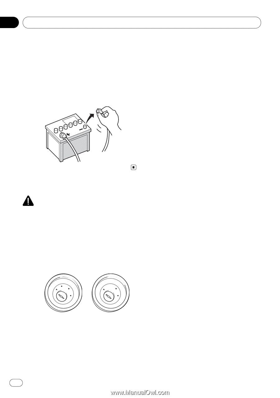
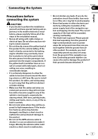
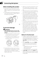
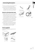
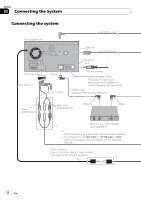
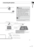
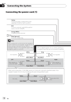
Section 03 Connecting the System Before installing this product ! This product is for vehicles with a 12-volt battery and negative grounding. Check the battery voltage of your vehicle before installation. ! To avoid shorts in the electrical system, be sure to disconnect the (-) battery cable before beginning installation. To prevent damage WARNING ! When replacing the fuse, be sure to only use a fuse of the rating prescribed on this product. ! When disconnecting a connector, pull the connector itself. Do not pull the lead, as you may pull it out of the connector. ! This product cannot be installed in a vehicle without ACC (accessory) position on the ignition switch. F ACC O F O OF OF N STAR N STAR T T ACC position No ACC position ! To avoid short-circuiting, cover the disconnected lead with insulating tape. It is especially important to insulate all unused speaker leads, which if left uncovered may cause a short circuit. ! Attach the connectors of the same color to the corresponding colored port, i.e., blue connector to the blue port, black to black, etc. ! Refer to the owner's manual for details on connecting the power amp and other units, then make connections accordingly. ! Since a unique BPTL circuit is employed, do not directly ground the * side of the speaker lead or connect the * sides of the speaker leads together. Be sure to connect the * side of the speaker lead to the * side of the speaker lead on this navigation system. ! If the RCA pin jack on this product will not be used, do not remove the caps attached to the end of the connector. ! Never connect speakers with an output rating of less than 50 W channel or impedance outside of the 4 ohms to 8 ohms specifications to your navigation system. Connecting speakers with output and/or impedance values other than those noted here may result in the speakers catching fire, emitting smoke, or becoming damaged. Notice for the blue lead ! A signal is output through the blue lead to control the antenna of your vehicle. The timing varies depending on the setting. (For more detailed information on changing [Ant CTRL] mode, refer to "Operation Manual".) ! When [Ant CTRL] mode is set to [Radio], the vehicle's antenna can be stowed or turned off by following the instructions below. - Change the source from radio (AM or FM) to another source. - Turn the source off - Turn off the ignition switch (ACC OFF) ! If [Ant CTRL] mode is set to [Power], the vehicle's antenna can be stowed or turned off only when the ignition switch is turned off (ACC OFF). 6 En
-
 1
1 -
 2
2 -
 3
3 -
 4
4 -
 5
5 -
 6
6 -
 7
7 -
 8
8 -
 9
9 -
 10
10 -
 11
11 -
 12
12 -
13
-
14
-
15
-
16
-
17
-
18
-
19
-
20
-
21
-
22
-
23
-
24
-
25
-
26
-
27
-
28
-
29
-
30
-
31
-
32
-
33
-
34
-
35
-
36
-
37
-
38
-
39
-
40
-
41
-
42
-
43
-
44
-
45
-
46
-
47
-
48
-
49
-
50
-
51
-
52
-
53
-
54
-
55
-
56
-
57
-
58
 |
 |