Pioneer DVD-106S Operating Instructions - Page 8
DC input, Host IDE interface, Device configuration jumper, Audio output, Digital audio output - specification
 |
View all Pioneer DVD-106S manuals
Add to My Manuals
Save this manual to your list of manuals |
Page 8 highlights
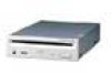
A HARDWARE TOUR REAR VIEW 39 1 21 4 15 1 40 24 1 0 98 7 6 6 DC input This is the power supply input for DC +5 V and +12 V. Pin Name Function 1 +12 Power supply input for DC +12 V. 2 G Ground. 3 G Ground. 4 +5 Power supply input for DC +5 V. 7 Host IDE interface This is a 40 pin I/O connector according to the ATA specifications. 8 Device configuration jumper This is the jumper switch for selection of the drive use mode and supporting PC. Short-circuit socket is attached for the setting attached : on not attached : off Pin Name Function 1 MA on The drive is used in master mode. 2 SL on The drive is used in slave mode. 3 CS on Mode for drive setting by CSEL of the IDE interface. 4 Reserved. 5 Reserved. 9 Audio output This is a connector for output of analog audio. As a Molex 70553 type connecter is used, select a matching connection cable. Pin Name Function 1 L Left channel audio output. 2 G Ground. 3 G Ground. 4 R Right channel audio output. 0 Digital audio output This is a connector for output of digital audio signal. Pin Name Function 1 GND Ground. 2 Digital Out Digital audio signal output. 8 En
-
 1
1 -
2
-
 3
3 -
 4
4 -
 5
5 -
 6
6 -
 7
7 -
 8
8 -
 9
9 -
 10
10 -
 11
11 -
 12
12 -
 13
13 -
14
-
15
-
16
-
17
-
18
-
19
-
20
-
21
-
22
-
23
-
24
-
25
-
26
-
27
-
28
-
29
-
30
-
31
-
32
-
33
-
34
-
35
-
36
-
37
-
38
-
39
-
40
-
41
-
42
-
43
-
44
-
45
-
46
-
47
-
48
 |
 |
