Pioneer GM-X354 Owners Manual - Page 10
Connecting the Speaker wires
 |
View all Pioneer GM-X354 manuals
Add to My Manuals
Save this manual to your list of manuals |
Page 10 highlights
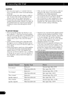
Connecting the Unit Connecting the Speaker wires The speaker output mode can be four-channel, three-channel (stereo + mono) or two-channel (stereo, mono). Connect the speaker leads to suit the mode according to the figures shown below. • When either the RCA input or the speaker input is connected, RCA output becomes functional. Do not connect both the RCA input and the speaker input at the same time. Four-channel mode Input Select Switch For two-channel input, slide this switch to the left. For four-channel input, slide this switch to the right. Speaker input terminal A Speaker input terminal B (Left) Speaker out A (Right) Speaker output terminal Speaker input connector Three-channel mode Input Select Switch For two-channel input, slide this switch to the left. For four-channel input, slide this switch to the right. Speaker input terminal A Speaker input terminal B Speaker input connector 9 (Right) Speaker out B (Left) (Left) Speaker out A (Right) Speaker output terminal Speaker out B (Mono)
-
 1
1 -
2
-
3
-
4
-
 5
5 -
 6
6 -
 7
7 -
 8
8 -
 9
9 -
 10
10 -
 11
11 -
 12
12 -
 13
13 -
 14
14 -
 15
15 -
16
-
17
-
18
-
19
-
20
-
21
-
22
-
23
-
24
-
25
-
26
-
27
-
28
-
29
-
30
-
31
-
32
-
33
-
34
-
35
-
36
-
37
-
38
-
39
-
40
-
41
-
42
-
43
-
44
-
45
-
46
-
47
-
48
-
49
-
50
-
51
-
52
-
53
-
54
-
55
-
56
-
57
-
58
-
59
-
60
-
61
-
62
-
63
-
64
-
65
-
66
-
67
-
68
-
69
-
70
-
71
-
72
-
73
-
74
-
75
-
76
 |
 |
