Pioneer GM-X822 Service Manual - Page 26
Connecting the Speaker, wires, Component Guide, Setting the Filter Constant
 |
View all Pioneer GM-X822 manuals
Add to My Manuals
Save this manual to your list of manuals |
Page 26 highlights
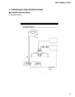
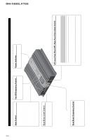
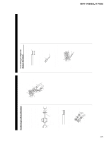
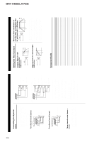
GM-X822,X722 26 Connecting the Speaker wires The speaker output mode can be two-channel (stereo), one-channel (mono), or threechannel (stereo + mono). Connect the speaker leads to suit the mode according to figures on the following pages. • When connecting to the speaker input, do not connect the RCA output. • When connecting to the RCA input, do not connect the speaker input. Two-channel mode (stereo) (Left) Speaker (Right) One-channel mode (mono) Speaker (Mono) Three-channel mode (stereo + mono) The power amplifier is basically a twochannel/one-channel bridgeable amplifier, but three channels can be achieved by combining the stereo and mono modes using inductors and capacitors. Three-channel mode, two-way system C1 Mid-high (Left) L1 Woofer (Mono) C1 Mid-high (Right) Three-channel mode, three-way system C1 L2 C2 L1 L2 C2 High/mid-high (Left) Mid/mid-bass (Left) Woofer/sub-woofer (Mono) Mid/mid-bass (Right) High/mid-high (Right) • Inductors (L1 and L2 in the diagrams) act as low-pass filters. Capacitors (C1 and C2 in the diagrams) act as high-pass filters. Inductors (L) are used for the woofer/sub-woofer, and capacitors (C) are used for the high/mid-high. • Remember when bridging an amplifier it will see only half of the original speaker impedance. Therefore, you must use speakers that have ratings of 4 ohms or higher. If you use speakers that have lower impedance ratings it may cause damage to the amplifier. • When the inductors and capacitors are connected to the speaker wires, secure or solder them so they cannot be pulled loose. Tape or use heat shrink on the joints to prevent short circuits. Setting the Filter Constant Low-pass filter (for subwoofer/woofer): 6 dB/octave 0dB L1 -6dB f fC 2f C High-pass filter (for mid/mid-high): 6 dB/octave C1 0dB -6dB fC fC f 2 Band-pass filter (combination of low-pass filter and high-pass filter for mid-bass/mid): 6 dB/octave L2 C2 0dB -6dB f f CL CL 2 fCH 2f CH • A multi-channel system can be set up using a combination of filters. The inductance (L) and capacitance (C) will determine the frequency (fc) that the speaker will reproduce. Refer to the chart below to determine the components required. • Use the capacitors specified. Non-polarized capacitors rated at over ±25 V should be used for C1 and C2 in the diagram. Because of the voltage output of the amplifier, it is very important to use non-polarized capacitors rated at or over 25 V. This will prevent a safety hazard. Component Guide Speaker load Impedance fc (Hz) 50 80 125 200 320 500 800 1,250 2,000 3,200 5,000 8,000 10,000 2 Ω L (mH) C (µF) 6.4 1,600 4.0 1,000 2.5 640 1.6 400 1.0 250 0.64 160 0.4 100 0.25 64 0.16 40 0.1 25 0.06 16 0.04 10 0.03 8 4 Ω L (mH) C (µF) 12.70 800.0 8.00 500.0 5.10 300.0 3.20 200.0 2.00 125.0 1.30 80.0 0.80 50.0 0.50 30.0 0.30 20.0 0.20 12.5 0.13 8.0 0.08 5.0 0.06 4.0 8 Ω L (mH) C (µF) 25.50 400.0 16.00 250.0 10.00 160.0 6.40 100.0 4.00 62.0 2.60 40.0 1.60 25.0 1.00 16.0 0.64 10.0 0.40 6.2 0.26 4.0 0.16 2.5 0.13 2.0
-
 1
1 -
2
-
3
-
4
-
5
-
6
-
7
-
8
-
9
-
10
-
11
-
12
-
13
-
14
-
15
-
16
-
17
-
18
-
19
-
20
-
 21
21 -
 22
22 -
 23
23 -
 24
24 -
 25
25 -
 26
26 -
 27
27 -
 28
28
 |
 |
