Pioneer GM-X822 Service Manual - Page 8
Schematic Diagram
 |
View all Pioneer GM-X822 manuals
Add to My Manuals
Save this manual to your list of manuals |
Page 8 highlights
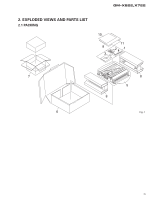
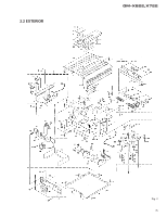
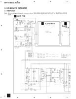
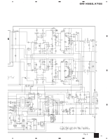
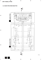
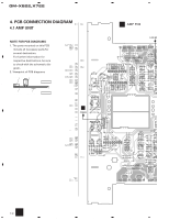
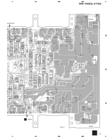
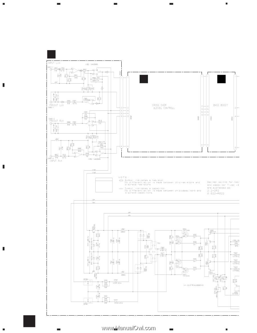
1 2 3 4 GM-X822,X722 3. SCHEMATIC DIAGRAM 3.1 AMP UNIT A Note: When ordering service parts, be sure to refer to "EXPLODED VIEWS AND PARTS LIST" or "ELECTRICAL PARTS LIST". A AMP PCB -10dBs -7.6dBs -10.2dBs B AUDIO PCB C BASS PCB B 15.5V -15.5V AMP UNIT Consists of AMP PCB AUDIO PCB BASS PCB -35V -35-30V C 30V -30V D A 8 1 2 3 4
-
 1
1 -
2
-
 3
3 -
 4
4 -
 5
5 -
 6
6 -
 7
7 -
 8
8 -
 9
9 -
 10
10 -
 11
11 -
 12
12 -
 13
13 -
14
-
15
-
16
-
17
-
18
-
19
-
20
-
21
-
22
-
23
-
24
-
25
-
26
-
27
-
28
 |
 |
GM-X822,X722
A
1
2
3
4
B
C
D
1
2
3
4
A
B
C
AMP PCB
AUDIO PCB
BASS
PCB
AMP UNIT
AMP PCB
AUDIO PCB
BASS PCB
Consists of
-10dBs
-7.6dBs
-10.2dBs
30V
-30V
-35-30V
-35V
15.5V
-15.5V
3. SCHEMATIC DIAGRAM
3.1 AMP UNIT
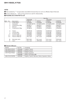
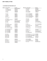
Note:
When ordering service parts, be sure to refer to "EXPLODED VIEWS AND PARTS LIST" or "ELECTRICAL PARTS
LIST".
8
A