Pioneer GM-X924 Service Manual - Page 14
Pcb Connection Diagram
 |
View all Pioneer GM-X924 manuals
Add to My Manuals
Save this manual to your list of manuals |
Page 14 highlights
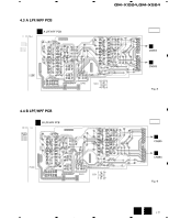
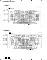
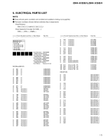
1 2 GM-X1024,GM-X924 3 4 NOTE FOR PCB DIAGRAMS 1. The parts mounted on this PCB include all necessary parts for several destination. 4. PCB CONNECTION DIAGRAM For further information for respective destinations, be sure to check with the schematic diagram. A 4.1 AMP UNIT A AMP UNIT B CN856 B C D A 14 1 OUTPUT INPUT 2CH/4CH B E CN102 D CN552 C CN502 F CN302 B CN857 2 3 A 4
-
 1
1 -
2
-
3
-
4
-
5
-
6
-
7
-
8
-
 9
9 -
 10
10 -
 11
11 -
 12
12 -
 13
13 -
 14
14 -
 15
15 -
 16
16 -
 17
17 -
 18
18 -
 19
19 -
20
-
21
-
22
-
23
-
24
-
25
-
26
-
27
-
28
-
29
-
30
-
31
-
32
-
33
 |
 |

2CH/4CH
INPUT
OUTPUT
A
B
A
AMP UNIT
B
CN856
E
CN102
D
CN552
C
CN502
F
CN302
B
CN857
14
GM-X1024,GM-X924
A
1
2
3
4
B
C
D
2
3
4
NOTE FOR PCB DIAGRAMS
1. The parts mounted on this PCB include all necessary
parts for several destination.
For further information for respective destinations,
be sure to check with the schematic diagram.
4. PCB CONNECTION DIAGRAM
4.1 AMP UNIT
A
1