Pioneer GM-X924 Service Manual - Page 27
Disassembly
 |
View all Pioneer GM-X924 manuals
Add to My Manuals
Save this manual to your list of manuals |
Page 27 highlights
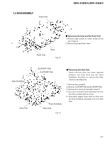
GM-X1024,GM-X924 7.2 DISASSEMBLY A Panel Unit A A BB BB A B C B A A A BC Panel Unit A Case Fig. 13 - Removing the Case and the Panel Unit 1. Remove eight screws A, seven screws B and two screws C. 2. Remove Case and Panel Units. D B LPF/HPF PCB A LPF/HPF PCB F D F Heat Sink(Sub) F E E F F F E E F F Amp Unit Heat Sink(Sub) Heat Sink Fig. 14 - Removing the Heat Sink Some silicone glue has been applied between the Heat Sink and the Heat Sink(Sub). therefore, to remove the Amp Unit from the Heat Sink. 1. Remove two screws D. 2. Remove A LPF/HPF PCB and B LPF/HPF PCB. 3. Remove four screws E and eight screws F. 4. Use 2 pcs. of screw E and insert them into the two holes marked with an arrow. 5. Alternately tighten them little by little until the Heat Sink(Sub) separates from the Heat Sink. 27
-
 1
1 -
2
-
3
-
4
-
5
-
6
-
7
-
8
-
9
-
10
-
11
-
12
-
13
-
14
-
15
-
16
-
17
-
18
-
19
-
20
-
21
-
 22
22 -
 23
23 -
 24
24 -
 25
25 -
 26
26 -
 27
27 -
 28
28 -
 29
29 -
 30
30 -
 31
31 -
 32
32 -
33
 |
 |
