Pioneer KEH-P2800 Service Manual - Page 41
Operations And Specifications - cd
 |
UPC - 012562458588
View all Pioneer KEH-P2800 manuals
Add to My Manuals
Save this manual to your list of manuals |
Page 41 highlights
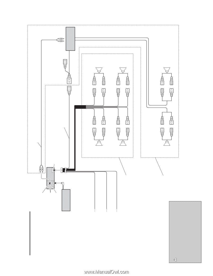
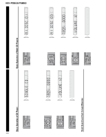
8. OPERATIONS AND SPECIFICATIONS Connection Diagram This Unit Rear output Antenna jack Multi-CD player (sold separately) Connecting cords with RCA pin plugs (sold separately) Fuse To system control terminal of the power amp or Autoantenna relay control terminal. (Max. 300 mA 12 V DC) System remote Blue/white control To vehicle (metal) body. Black To electric terminal controlled by ignition switch (12 V DC) ON/OFF. To terminal always supplied with power regardless of ignition switch position. Red Yellow With a 2 speaker system, connect to the 2 speakers in the front or the rear. Left speaker + Front ≠ + Rear ≠ White White/black Gray Gray/black Green Green/black Violet Violet/black Right speaker + Front ≠ + Rear ≠ Power amp (sold separately) KEH-P2800,P3850 CAUTION • Cords for this unit and those for other units may be different colors even if they have the same function. When connecting this unit to another unit, refer to the supplied Installation manuals of both units and connect cords that have the same function. Use this for connections when you have the separately available amplifier. + Rear ≠ + Rear ≠ 41
-
 1
1 -
2
-
3
-
4
-
5
-
6
-
7
-
8
-
9
-
10
-
11
-
12
-
13
-
14
-
15
-
16
-
17
-
18
-
19
-
20
-
21
-
22
-
23
-
24
-
25
-
26
-
27
-
28
-
29
-
30
-
31
-
32
-
33
-
34
-
35
-
 36
36 -
 37
37 -
 38
38 -
 39
39 -
 40
40 -
 41
41 -
 42
42 -
 43
43 -
 44
44 -
 45
45 -
 46
46
 |
 |