Pioneer MJ-D707 Service Manual - Page 66
Panel Facilities And Specifications - minidisc recorder
 |
View all Pioneer MJ-D707 manuals
Add to My Manuals
Save this manual to your list of manuals |
Page 66 highlights
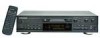
MJ-D707, MJ-17D 8. PANEL FACILITIES AND SPECIFICATIONS PANEL FACILITIES Main unit front panel TIMER REC OFF PLAY MJ-D707 MINIDISC RECORDER STANDBY POWER DIGITAL NR REPEAT A B TIME SKIP Î - OFF _ ON PLAY MODE REC MODE NAME CLIP DISPLAY / CHARA DISC LOADING MECHANISM ) EJECT 1 $ PUSH ENTER $ EDIT/NO NAME INPUT SELECTOR COAX ANALOG OPT REC LEVEL 456 3 7 2 8 1 0 9 10 1 3 SYNCHRO REC 8 7 PHONES LEVEL MIN MAX Legato Link Conversion 1 POWER switch 2 STANDBY indicator 3 TIMER switch 4 DIGITAL NR button 5 REPEAT button 6 A-B button 7 TIME SKIP button 8 MD insertion slot 9 MD eject (0) button p Jog dial Main unit rear panel Display window q EDIT/NO button w NAME button e INPUT SELECTOR switch r REC LEVEL control t SYNCHRO REC button y Record (¶) button u Headphones volume control i PHONES jack o Stop (7) button ; Pause (8) button a Play (3) button s Fast forward (¡) button d Fast reverse (1) button f Remote control sensor g DISPLAY/CHARA button h NAME CLIP button j REC MODE button k PLAY MODE button The illustration shows the U.S. model. LINE INPUT OUTPUT REC PLAY L R DIGITAL INPUT COAXIAL OPTICAL DIGITAL OUTPUT OPTICAL CONTROL IN OUT 1 Audio input jacks 2 Audio output jacks 3 Digital input jack (Coaxial) 4 Digital input jack (Optical) 5 Digital output jacks (Optical) 6 Control input jack ( U.S. model only ) 7 Control output jack ( U.S. model only ) ¶ To connect to equipment with the Pioneer Î mark ( U.S. model only ) Use a commercialy available miniplug cord (without load) to connect the CONTROL IN jack of this unit to the CONTROL OUT jack of equipment with the Î mark. This allows you intensified control of the system. ÷ When this unit is connected for systemcontrol, this unit cannot be controlled directly with the remote control unit. ÷ For further details, refer to the operating instructions of the equipment connected to this unit. 66
-
 1
1 -
2
-
3
-
4
-
5
-
6
-
7
-
8
-
9
-
10
-
11
-
12
-
13
-
14
-
15
-
16
-
17
-
18
-
19
-
20
-
21
-
22
-
23
-
24
-
25
-
26
-
27
-
28
-
29
-
30
-
31
-
32
-
33
-
34
-
35
-
36
-
37
-
38
-
39
-
40
-
41
-
42
-
43
-
44
-
45
-
46
-
47
-
48
-
49
-
50
-
51
-
52
-
53
-
54
-
55
-
56
-
57
-
58
-
59
-
60
-
 61
61 -
 62
62 -
 63
63 -
 64
64 -
 65
65 -
 66
66 -
 67
67 -
 68
68
 |
 |
